14-2
Cisco ONS 15454 Procedure Guide, R5.0
December 2004
Chapter 14 Add and Remove Nodes
NTP-A212 Add a BLSR Node
NTP-A212 Add a BLSR Node
Caution Adding a BLSR node can be service affecting and should be performed during a maintenance window.
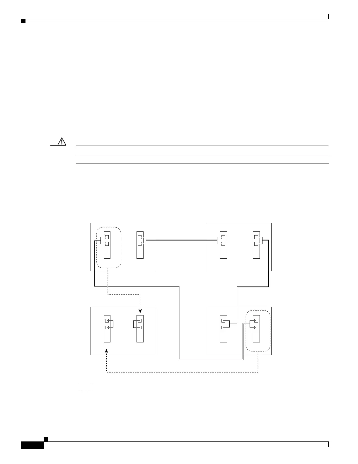
Step 1 Draw a diagram of the BLSR where you will add the node. In the diagram, identify the east and west
BLSR OC-N trunk (span) cards that will connect to the new node. This information is essential to
complete this procedure without error. Figure 14-1 shows a drawing of a three-node, two-fiber BLSR
that uses Slots 5 and 12 for the BLSR trunk cards. The dashed arrow shows the new fiber connections
that will be made to add the fourth node to the BLSR.
Figure 14-1 Three-Node, Two-Fiber BLSR Before a Fourth Node Is Added
Purpose This procedure expands a BLSR by adding a node.
Tools/Equipment Fiber for new node connections
Prerequisite Procedures Cards must be installed and node turn-up procedures completed on the
node that will be added to the BLSR. See Chapter 2, “Install Cards and
Fiber-Optic Cable,” and Chapter 4, “Turn Up Node.”
Required/As Needed As needed
Onsite/Remote Onsite
Security Level Provisioning or higher
78740
West East
West East
West East
West East
Slot 5
Tx
Rx
Slot 12
Tx
Rx
New Node
Slot 5
Tx
Rx
Slot 12
Tx
Rx
Node 2Node 1
Slot 5
Tx
Rx
Slot 12
Tx
Rx
Node 3
Slot 5
Tx
Rx
Slot 12
Tx
Rx
Working and protect fibers
New fiber connections

 Loading...


