17-26
Cisco ONS 15454 Procedure Guide, R5.0
March 2005
Chapter 17 DLPs A1 to A99
DLP-A21 Install LAN Wires on the Backplane
DLP-A21 Install LAN Wires on the Backplane
Note Rather than using the LAN wires, you can use the LAN connection port on the TCC2/TCC2P if
preferred. Use either the backplane connection or the TCC2/TCC2P front connection. You cannot use
the LAN backplane pins and the LAN connection port on the TCC2/TCC2P simultaneously; however, it
is possible for you to make a direct connection from a computer to the LAN connection port on the
TCC2/TCC2P while the LAN backplane pins are in use as long as the computer that is connected directly
to the TCC2/TCC2P is not connected to a LAN.
Step 1 Using #22 or #24 AWG (0.51 mm² or 0.64 mm²) wire or CAT-5 UTP Ethernet cable, wrap the wires on
the appropriate wire-wrap pins according to local site practice.
Caution Cross talk might result if both receive (Rx) and transmit (Tx) pins connect on the same twisted pair of
wires from the CAT-5 cable. The two Tx pins need to be on one twisted pair, and the two Rx pins need
to be on another twisted pair.
A frame ground pin is located beneath each pin field (FG2 for the LAN pin field). Wrap the ground shield
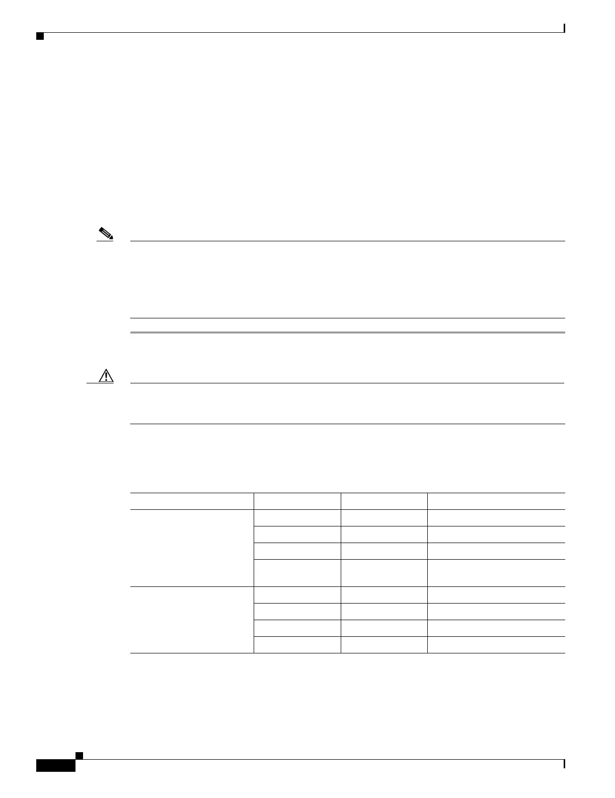
of the LAN interface cable to the frame ground pin. Table 17-2 shows the LAN pin assignments.
Purpose This task installs the LAN wires on the backplane.
Tools/Equipment Wire wrapper
#22 or #24 AWG (0.51 mm² or 0.64 mm²) wire, preferably CAT-5 UTP
Prerequisite Procedures None
Required/As Needed As needed
Onsite/Remote Onsite
Security Level None
Table 17-2 LAN Pin Assignments
Pin Field Backplane Pins RJ-45 Pins Function/Color
LAN 1
Connecting to data
circuit-terminating
equipment (DCE) (a hub or
switch); the ONS 15454 is a
DCE
B2 1 TX+ white/green
A2 2 TX– green
B1 3 RX+ white/orange
A1 6 RX– orange
LAN 1
Connecting to data terminal
equipment (DTE) (a
PC/workstation or router)
B1 1 RX+ white/green
A1 2 RX– green
B2 3 TX+ white/orange
A2 6 TX– orange

 Loading...


