17-37
Cisco ONS 15454 Procedure Guide, R5.0
March 2005
Chapter 17 DLPs A1 to A99
DLP-A30 Install Ferrites to Power Cabling
Caution When routing the long UBIC-H combination 735/734 cables, do not stretch or force them by pulling on
one end. They must be properly laid into the cable racks to prevent the splices from being broken or
shorted.
Note SMB EIAs feature cable-management eyelets for tie wrapping or lacing cables to the cover
panel.
Step 3 Return to your originating procedure (NTP).
DLP-A30 Install Ferrites to Power Cabling
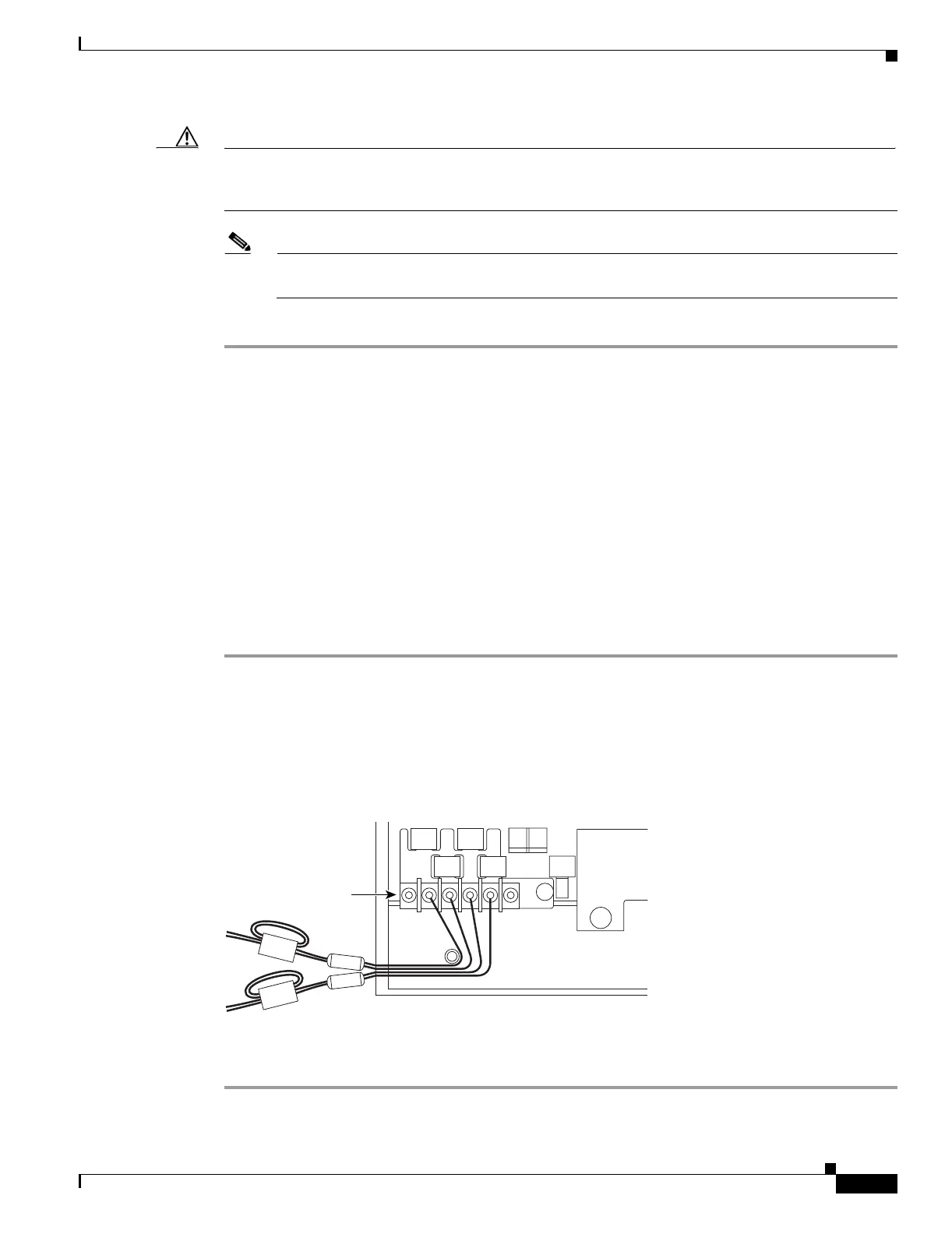
Step 1 Wrap the cables once around and through the block ferrites and pull the cables straight through the oval
ferrites.
Step 2 Place the oval ferrite as close to the power terminals as possible, between the ONS 15454 and the block
ferrite, as shown in Figure 17-18. The block ferrite should be within 5 to 6 inches (127 to 152 mm) of
the power terminals.
Figure 17-18 Attaching Block and Oval Ferrites to Power Cabling
Step 3
Return to your originating procedure (NTP).
Purpose This task attaches ferrites to power cabling. Use a single oval ferrite
(TDK ZCAT2035-0930) and a single block ferrite (Fair Rite 0443164151)
for each pair of cables (BAT1/RET1 [A] and BAT2/RET2[B]).
Tools/Equipment Oval and block ferrites
Prerequisite Procedures None
Required/As Needed Required
Onsite/Remote Onsite
Security Level None
Power terminals
32087

 Loading...


