5-21
Cisco ONS 15454 Procedure Guide, R5.0
December 2004
Chapter 5 Turn Up Network
NTP-A44 Provision Path Protection Nodes
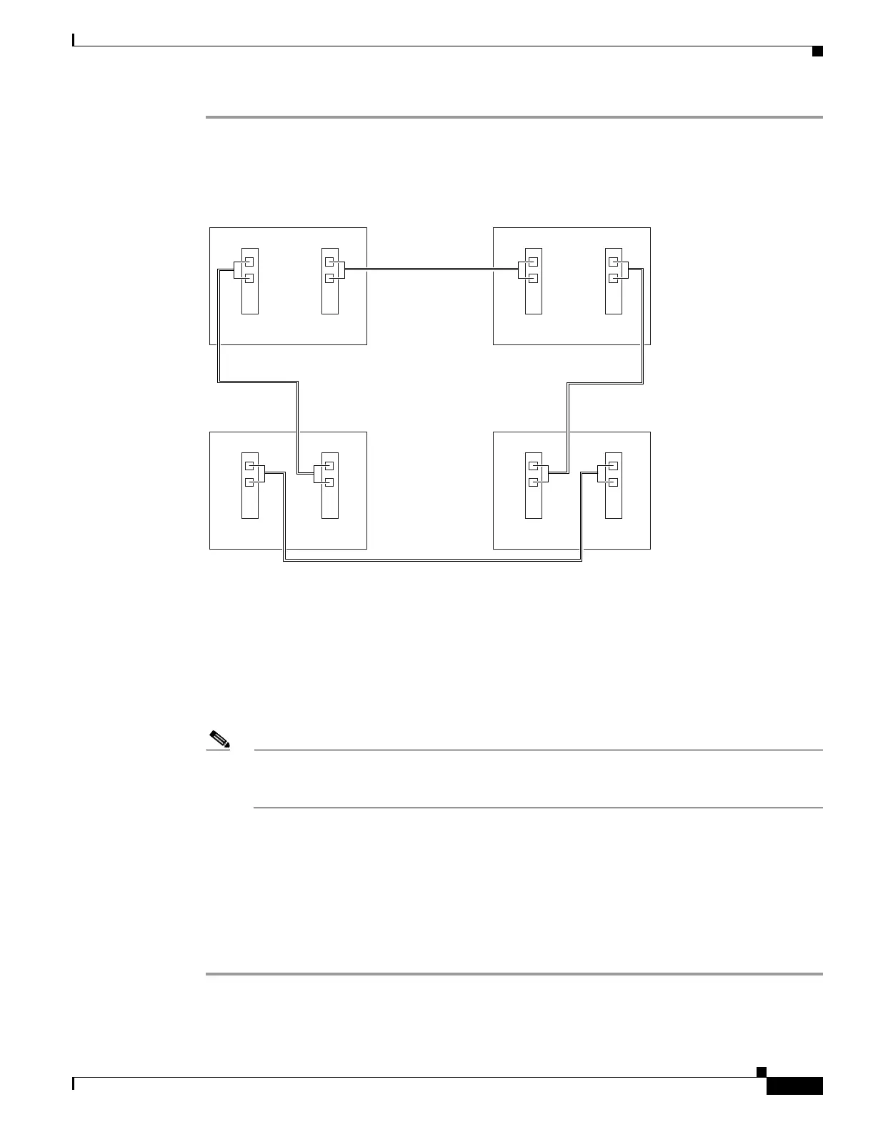
Step 1 Verify that the fiber is correctly connected to the path protection trunk (span) OC-N cards similar to
Figure 5-6. See the “DLP-A43 Install Fiber-Optic Cables for Path Protection Configurations” task on
page 17-49.
Figure 5-6 Path Protection Fiber Connection Example
Step 2
Log into an ONS 15454 in the path protection you are turning up. See the “DLP-A60 Log into CTC”
task on page 17-66. If you are already logged in, continue with Step 3.
Step 3 Complete the “DLP-A377 Provision Section DCC Terminations” task on page 20-61 or for the two
cards/ports that will serve as the path protection ports on the node, for example, Slot 5 (OC-48)/Node 1
and Slot 12 (OC-48)/Node 1. (Alternatively, if additional bandwidth is needed for CTC management,
complete the “DLP-A378 Provision Line DCC Terminations” task on page 20-62.)
Note If an ONS 15454 is not connected to a corporate LAN, DCC or LDCC provisioning must be
performed through a direct (craft) connection. Remote provisioning is possible only after all
nodes in the network have DCC or LDCC terminations provisioned to in-service OC-N ports.
Step 4 Repeat Steps 2 and 3 for each node in the path protection.
Step 5 As needed, complete the “DLP-A380 Provision a Proxy Tunnel” task on page 20-63.
Step 6 As needed, complete the “DLP-A381 Provision a Firewall Tunnel” task on page 20-64.
Step 7 As needed, complete the “DLP-A367 Create a Provisionable Patchcord” task on page 20-51.
Step 8 Complete the “NTP-A177 Path Protection Acceptance Test” procedure on page 5-22.
Stop. You have completed this procedure.
68120
Node 1
Slot 5
Tx
Rx
Slot 12
Tx
Rx
Node 4
Slot 5
Tx
Rx
Slot 12
Tx
Rx
Node 2
Slot 5
Tx
Rx
Slot 12
Tx
Rx
Node 3
Slot 5
Tx
Rx
Slot 12
Tx
Rx

 Loading...


