17-72
Cisco ONS 15454 Procedure Guide, R5.0
March 2005
Chapter 17 DLPs A1 to A99
DLP-A64 Set the IP Address, Default Router, and Network Mask Using the LCD
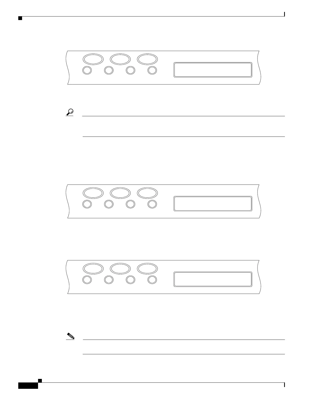
Figure 17-29 Changing the IP Address
Step 4
Push the Slot button to move to the IP address or subnet mask digit you need to change. The selected
digit flashes.
Tip The Slot, Status, and Port button positions correspond to the command position on the LCD. For
example, in Figure 17-29, you press the Slot button to invoke the Next command and the Port
button to invoke the Done command.
Step 5 Press the Port button to cycle the IP address or subnet mask to the correct digit.
Step 6 When the change is complete, press the Status button to return to the Node menu.
Step 7 Repeatedly press the Port button until the Save Configuration option appears (Figure 17-30).
Figure 17-30 Selecting the Save Configuration Option
Step 8
Press the Status button to choose the Save Configuration option.
A Save and REBOOT message appears (Figure 17-31).
Figure 17-31 Saving and Rebooting the TCC2/TCC2P
Step 9
Press the Slot button to apply the new IP address configuration or press Port to cancel the configuration.
Saving the new configuration causes the TCC2/TCC2P cards to reboot. During the reboot, a “Saving
Changes - TCC Reset” message displays on the LCD. The LCD returns to the normal alternating display
after the TCC2/TCC2P reboot is complete.
Note The IP address and default router must be on the same subnet. If not, you cannot apply the
configuration.
FAN FAIL
Slot
172.020.214.107
<Next Done Mod>
44090
CRIT MAJ MIN
Status Port
FAN FAIL
Slot
Slot-0
Status=Save Cfg.
44091
CRIT MAJ MIN
Status Port
FAN FAIL
Slot
Save and REBOOT?
<Apply Revert>
44092
CRIT MAJ MIN
Status Port

 Loading...


