18-63
Cisco ONS 15454 Procedure Guide, R5.0
March 2007
Chapter 18 DLPs A100 to A199
DLP-A190 Install a UBIC-V EIA
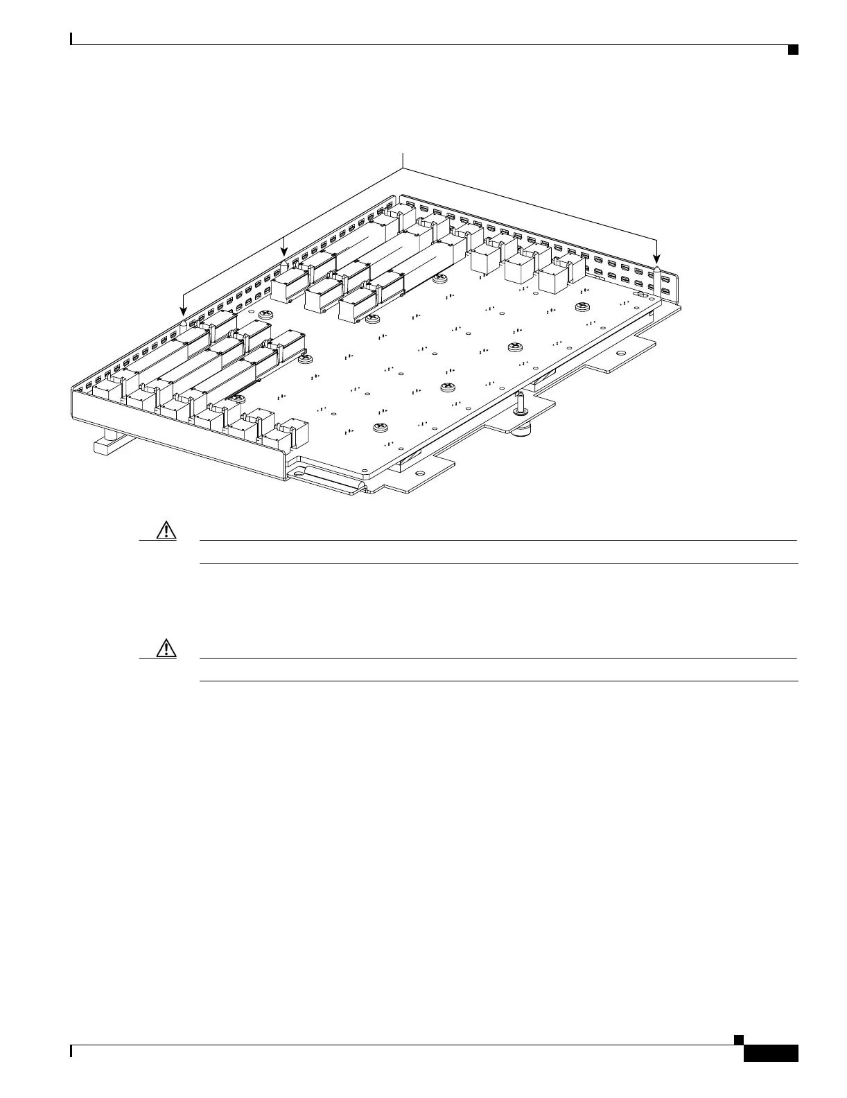
Figure 18-7 UBIC-V Alignment Pins
Caution Do not force the UBIC-V EIA onto the shelf if you feel strong resistance.
Step 7 Locate the three jack screws on the UBIC-V (Figure 18-8). Starting with any jack screw, tighten the
thumb screw a few turns and move to the next one, turning each thumb screw a few turns at a time until
all three screws are hand tight (Figure 18-9).
Caution Tightening the jack screws unevenly could cause damage to the UBIC-V connectors.
UBIC alignment pins
120367

 Loading...


