17-23
Cisco ONS 15454 Procedure Guide, R5.0
March 2005
Chapter 17 DLPs A1 to A99
DLP-A19 Install Alarm Wires on the Backplane
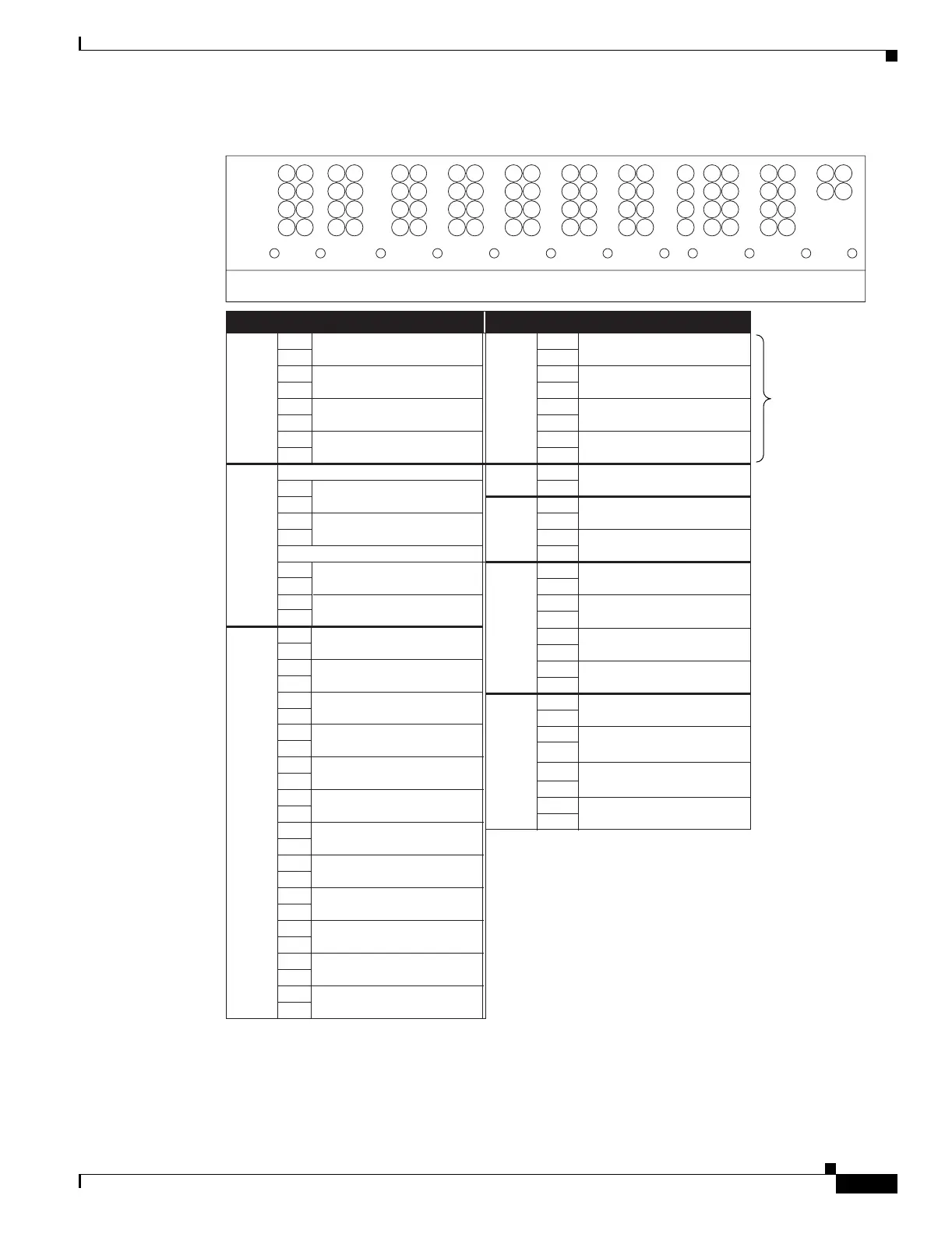
Figure 17-11 Cisco ONS 15454 Backplane Pinouts (Release 3.4 or Later)
Figure 17-12 calls out the environmental alarm pins on the backplane for Release 3.4 or later.
1
2
3
4
A
FG4FG3FG2FG1
BITS LAN
1
2
3
4
AB
1
2
3
4
AB
IN
1
2
3
4
AB
IN/OUT
FG6FG5
7
8
95
106
ABAB
ENVIRONMENTAL ALARMS
IN
ACO
FG7
1
2
3
4
IN
AB
FG8
1
2
3
4
AB
MODEM
FG9
1
2
3
4
A
CRAFT
AUDVIS
FG10
1
2
3
4
AB
LOCAL ALARMS
IN
FG12FG11
11
12
ABB
83020
Field Pin Function Field Pin Function
BITS A1 BITS Output 2 negative (–)
ENVIR
ALARMS
IN/OUT
N/O
A1/A13 Normally open output pair number 1
B1 BITS Output 2 positive (+) B1/B13
A2 BITS Input 2 negative (–) A2/A14 Normally open output pair number 2
B2 BITS Input 2 positive (+) B2/B14
A3 BITS Output 1 negative (–) A3/A15 Normally open output pair number 3
B3 BITS Output 1 positive (+) B3/B15
A4 BITS Input 1 negative (–) A4/A16 Normally open output pair number 4
B4 BITS Input 1 positive (+) B4/B16
LAN Connecting to a hub, or switch ACO A1 Normally open ACO pair
A1 B1
B1 CRAFT A1 Receive (PC pin #2)
A2 A2 Transmit (PC pin #3)
B2 A3 Ground (PC pin #5)
A4 DTR (PC pin #4)
LOCAL
ALARMS
AUD
(Audible)
N/O
N/O
A1 Alarm output pair number 1: Remote
audible alarm.
B1 B1
ENVIR
ALARMS
IN
A2 Alarm output pair number 2: Critical
audible alarm.
B2
A3 Alarm output pair number 3: Major
audible alarm.
A1
B3
B1
A4 Alarm output pair number 4: Minor
audible alarm.
A2
B4
B2
LOCAL
ALARMS
VIS
(Visual)
A1 Alarm output pair number 1: Remote
visual alarm.
A3
B1
A2 Alarm output pair number 2: Critical
visual alarm.
B2
A3 Alarm output pair number 3: Major
visual alarm.
B3
A4 Alarm output pair number 4: Minor
visual alarm.
B4
A1
A2
B3
A4
B4
RJ-45 pin 2 TX–
RJ-45 pin 1 TX+
RJ-45 pin 2 RX–
RJ-45 pin 1 RX+
RJ-45 pin 6 TX–
Alarm input pair number 1: Reports
closure on connected wires.
Alarm input pair number 2: Reports
closure on connected wires.
Alarm input pair number 3: Reports
closure on connected wires.
Alarm input pair number 4: Reports
closure on connected wires.
A5
B5
Alarm input pair number 5: Reports
closure on connected wires.
A6
B6
Alarm input pair number 6: Reports
closure on connected wires.
A7
B7
Alarm input pair number 7: Reports
closure on connected wires.
A8
B8
Alarm input pair number 8: Reports
closure on connected wires.
A9
B9
Alarm input pair number 9: Reports
closure on connected wires.
A10
B10
Alarm input pair number 10: Reports
closure on connected wires.
A11
B11
Alarm input pair number 11: Reports
closure on connected wires.
A12
B12
Alarm input pair number 12: Reports
closure on connected wires.
Connecting to a PC/Workstation or router
RJ-45 pin 3 TX+
B2
RJ-45 pin 3 RX+
RJ-45 pin 6 RX–
If you are using an
AIC-I card, contacts
provisioned as OUT
are 1-4. Contacts
provisioned as IN
are 13-16.

 Loading...


