7-12
Cisco ONS 15454 Procedure Guide, R5.0
December 2004
Chapter 7 Manage Alarms
NTP-A258 Provision External Alarms and Controls on the Alarm Interface Controller-International
Step 1 Verify the backplane wiring using the following substeps. If you are using the AEP, see the “NTP-A119
Install the Alarm Expansion Panel” procedure on page 1-12. Otherwise, see the “NTP-A8 Attach Wires
to Alarm, Timing, LAN, and Craft Pin Connections” procedure on page 1-15 for information about the
ONS 15454 backplane pins.
a. For external alarms, verify that the external device relays are wired to the ENVIR ALARMS IN
backplane pins.
b. For external controls, verify that the external device relays are wired to the ENVIR ALARMS OUT
backplane pins.
Step 2 Complete the “DLP-A60 Log into CTC” task on page 17-66. If you are already logged in, continue with
Step 2.
Step 3 In the node view, double-click the AIC-I card on the shelf graphic. The card view appears.
Step 4 Click the Provisioning > Card tabs.
Step 5 In the Alarm Contacts area, click the Add Extension radio button if you are using the AEP. Clicking this
option will choose the External Alarm input/output type and the AEP extension type; it will give you
access to 16 external alarm contacts.
Step 6 If you did not click Add Extension, in the Input/Output area, choose either External Alarm or External
Control. (External Alarm will limit your input/output options as explained in Step 5.) Choosing External
Control will enable both external alarms and external controls. This will convert four of the external
alarm contacts to external controls, leaving 12 available external control contacts. The extension type for
both options is AEP.
Step 7 Click Apply.
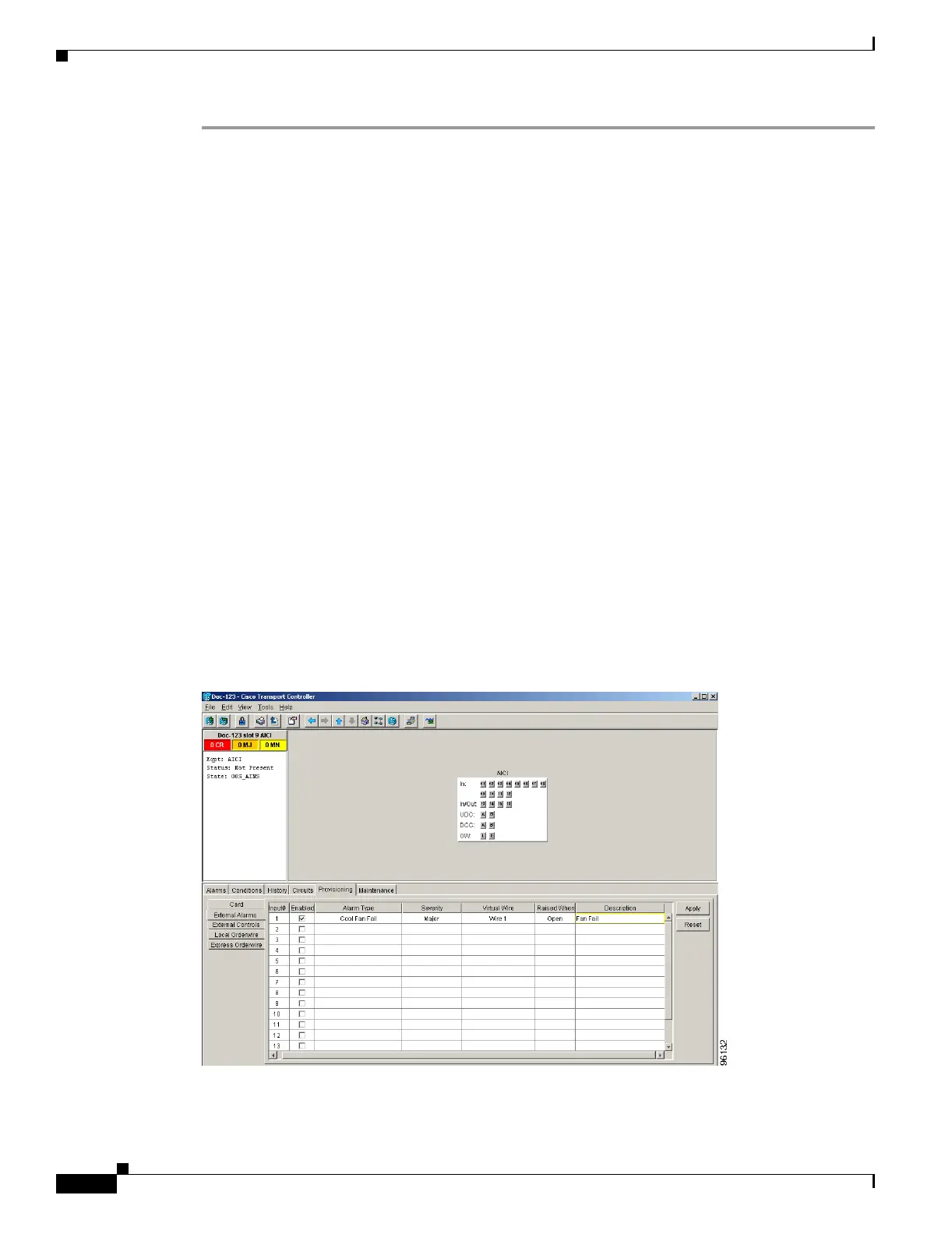
Step 8 If you are provisioning external alarms, click the External Alarms tab (Figure 7-5). If you are not
provisioning external alarms, skip Steps 9 through 11 and go to Step 12.
Figure 7-5 Provisioning External Alarms On The AIC-I Card
Step 9
For external alarms, complete the following fields:
 Loading...


