20-54
Cisco ONS 15454 Procedure Guide, R5.0
March 2005
Chapter 20 DLPs A300 to A399
DLP-A369 Provision an OC-N Circuit Route
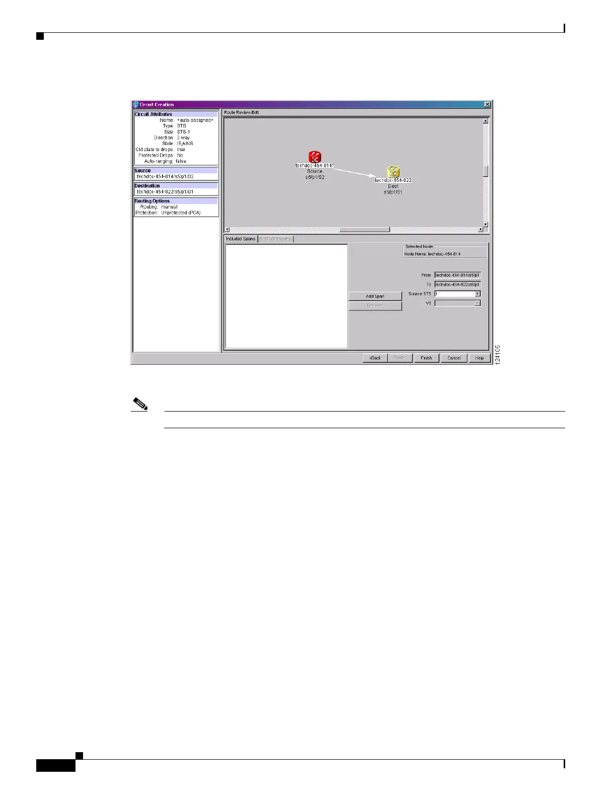
Figure 20-9 Manually Routing an OC-N Circuit
Step 3 If you want to change the source STS, adjust the Source STS field; otherwise, continue with Step 4.
Note The VT option is disabled for OC-N circuits.
Step 4 Click Add Span. The span is added to the Included Spans list and the span arrow turns blue.
Step 5 Repeat Steps 2 through 4 until the circuit is provisioned from the source to the destination node through
all intermediary nodes. If Fully Protected Path is checked in the Circuit Routing Preferences panel, you
must:
• Add two spans for all path protection or unprotected portions of the circuit route from the source to
the destination.
• Add one span for all BLSR or 1+1 portions of route from the source to the destination.
• Add primary spans for BLSR-DRI (dual-ring interconnect) from the source to the destination
through the primary nodes, and then add spans through the secondary nodes as an alternative route.
Figure 20-10 shows an example of a manually routed BLSR-DRI circuit. The circuit map shows all
span types: unprotected, BLSR, and protection channel access (PCA). PCA spans can only be
chosen as part of the secondary path.
 Loading...


