6-42
Cisco ONS 15454 Procedure Guide, R5.0
August 2005
Chapter 6 Create Circuits and VT Tunnels
NTP-A257 Create an Automatically Routed OC-N Circuit
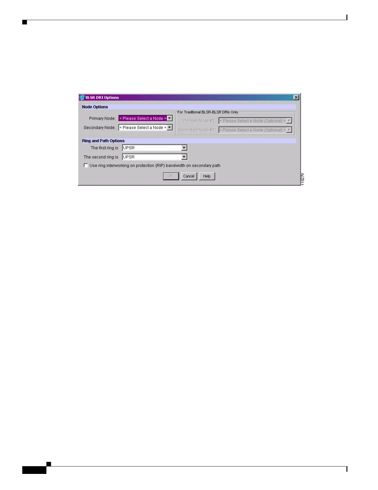
• Use ring interworking protection (RIP) on secondary path—Check this box to carry the
secondary spans on the protection channels. These spans will be preempted during a ring/span
switch.
Figure 6-11 Selecting BLSR DRI Primary and Secondary Node Assignments
e.
Click OK. The node information appears in the Required Nodes/Lines list, and the map graphic
indicates which nodes are primary and secondary.
f. In the Circuit Constraints for Automatic Routing area, click a node or span on the circuit map.
g. Click Include to include the node or span in the circuit, or click Exclude to exclude the node or span
from the circuit. The order in which you choose included nodes and spans is the order in which the
circuit will be routed. Click spans twice to change the circuit direction. If you are creating a path
protection to BLSR traditional handoff, exclude the unprotected links from the primary node
towards the secondary node. If you are creating a path protection to BLSR integrated handoff,
exclude unnecessary DRIs on the path protection segments.
h. Review the circuit constraints. To change the circuit routing order, choose a node in the
Required Nodes/Lines lists and click the Up or Down buttons to change the circuit routing order.
Click Remove to remove a node or span.
Step 19 If you selected Review Route Before Creation in Step 11, complete the following substeps; otherwise,
continue with Step 20.
a. Click Next.
b. Review the circuit route. To add or delete a circuit span, choose a node on the circuit route. Blue
arrows show the circuit route. Green arrows indicate spans that you can add. Click a span arrowhead,
then click Include to include the span or Remove to remove the span.
c. If the provisioned circuit does not reflect the routing and configuration you want, click Back to
verify and change circuit information. If the circuit needs to be routed to a different path, see the
“NTP-A295 Create a Manually Routed OC-N Circuit” procedure on page 6-43 to assign the circuit
route yourself.
Step 20 Click Finish. One of the following results occurs, based on the circuit properties you provisioned in the
Circuit Creation dialog box:
• If you entered more than 1 in the number of Circuits field and selected Auto-ranged, CTC
automatically creates the number of circuits entered in Number of Circuits. If auto-ranging cannot
complete all the circuits, for example, because sequential ports are unavailable on the source or
destination, a dialog box appears. Set the new source or destination for the remaining circuits, then
click Finish to continue auto-ranging. After completing the circuits, the Circuits window appears.

 Loading...


