9-6
Cisco ONS 15454 Procedure Guide, R5.0
December 2004
Chapter 9 Manage Circuits
NTP-A79 Create a J1 Path Trace
Step 8 Click Create Monitor Circuit.
Step 9 In the Circuit Destination section of the Circuit Creation wizard, choose the destination node, slot, port,
STS, VT, or DS1 for the monitored circuit.
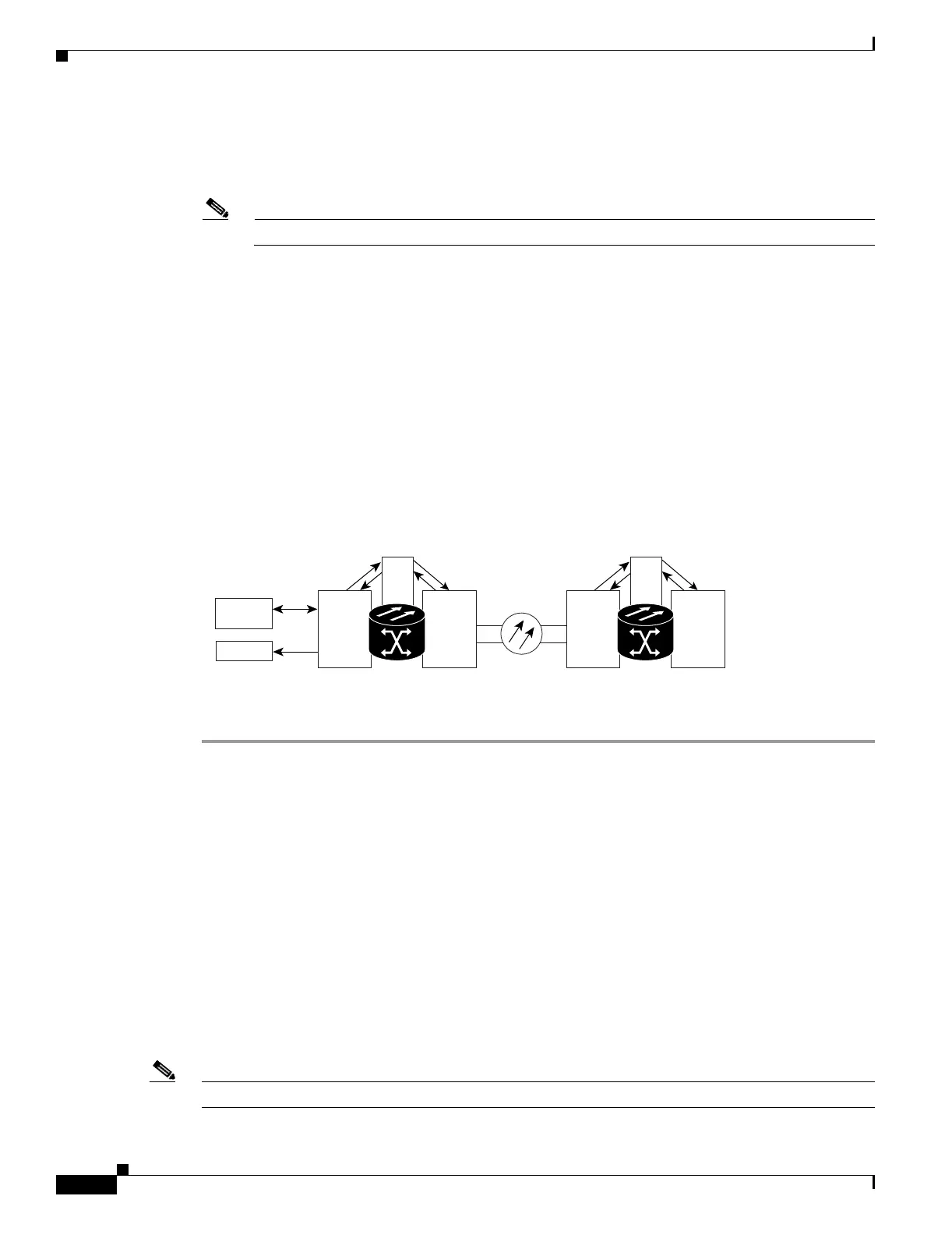
Note In the Figure 9-1 example, the monitor circuit destination is Port 2 on the EC1-12 card.
Step 10 Click Next.
Step 11 In the Circuit Routing Preferences area, review the monitor circuit information. If you want the monitor
circuit routed on a BLSR protection channel, click Protection Channel Access.
Step 12 Click Finish.
Step 13 In the Edit Circuit window, click Close. The new monitor circuit appears on the Circuits tab.
Figure 9-1 shows a sample monitor circuit setup. VT1.5 traffic is received by Port 1 of the EC1-12 card
at Node 1. To monitor the VT1.5 traffic, test equipment is plugged into Port 2 of the EC1-12 card and a
monitor circuit to Port 2 is provisioned in CTC. (Circuit monitors are one-way.) This example assumes
circuits have been created.
Figure 9-1 VT1.5 Monitor Circuit Received at an EC1-12 Port
Stop. You have completed this procedure.
NTP-A79 Create a J1 Path Trace
Note You cannot create a J1 path trace on a TL1-like circuit.
EC1-12
OC-N
XC
ONS 15454
Node 1
OC-N DS1-14
XC
ONS 15454
Node 2
VT1.5 Drop
VT1.5 Monitor
Test Set
Port 1
Port 2
Class 5
Switch
45157
Purpose This procedure creates a repeated, fixed-length string of characters used to
monitor interruptions or changes to circuit traffic.
Tools/Equipment ONS 15454 cards capable of transmitting and/or receiving path trace must
be installed. See Table 19-3 on page 19-47 for a list of cards.
Prerequisite Procedures Path trace can only be provisioned on OC-N (STS) circuits. See Chapter 6,
“Create Circuits and VT Tunnels” for OC-N circuit creation procedures.
Required/As Needed As needed
Onsite/Remote Onsite or remote
Security Level Provisioning or higher

 Loading...


