5-36
Cisco ONS 15454 Procedure Guide, R5.0
December 2004
Chapter 5 Turn Up Network
NTP-A46 Subtend a Path Protection from a BLSR
NTP-A46 Subtend a Path Protection from a BLSR
Note Path protection is the default ONS 15454 topology. It is available as soon as you install the path
protection OC-N cards, connect the OC-N fibers, and create the DCC terminations. Unlike the BLSRs,
ONS 15454 path protection configurations do not require explicit setup.
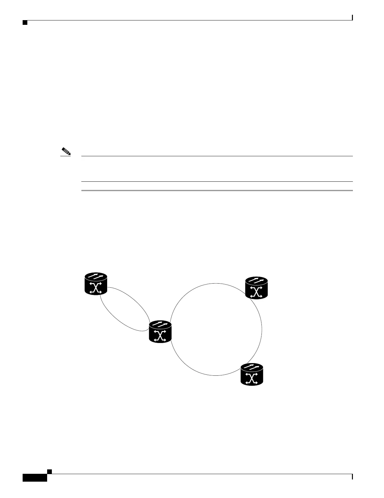
Step 1 In the node that will subtend the path protection (Node 3 in Figure 5-12), install the two OC-N cards that
will serve as the path protection trunk (span) cards (Node 3, Slots 6 and 13). See the “NTP-A16 Install
the OC-N Cards” procedure on page 2-6. If they are already installed, continue with Step 2.
Step 2 Attach fibers from these cards to the path protection trunk cards on the neighbor path protection node or
nodes. In Figure 5-12, Node 3/Slot 6 connects to Node 4/Slot 13, and Node 3/Slot 13 connects to Node
4/Slot 6.
Figure 5-12 Path Protection Subtended from a BLSR
Step 3 Complete the “DLP-A60 Log into CTC” task on page 17-66 at the ONS 15454 that will subtend the path
protection (Node 3 in the example).
Step 4 Complete the “DLP-A377 Provision Section DCC Terminations” task on page 20-61 for each OC-N card
that will carry the path protection. Alternatively, if additional bandwidth is needed for CTC
management, complete the“DLP-A378 Provision Line DCC Terminations” task on page 20-62.
Purpose This procedure subtends a path protection from an existing BLSR.
Tools/Equipment One BLSR node must have OC-N cards and fibers to carry the path
protection.
Prerequisite Procedures NTP-A175 Two-Fiber BLSR Acceptance Test, page 5-13 or
NTP-A176 Four-Fiber BLSR Acceptance Test, page 5-15
Required/As Needed As needed
Onsite/Remote Onsite
Security Level Provisioning and higher
Node 3
Node 1
Node 2
BLSR
Node 4
55303
Slot 13
Slot 12
Slot 12
Slot 12
Slot 13
Slot 6
Slot 5
Slot 5
Slot 5
Slot 6

 Loading...


