19-64
Cisco ONS 15454 Procedure Guide, R5.0
September 2005
Chapter 19 DLPs A200 to A299
DLP-A299 Initiate a BLSR Span Lock Out
Step 2 Choose the BLSR and click Edit.
Tip To move an icon to a new location, for example, to see BLSR channel (port) information more
clearly, you can drag and drop icons on the Edit BLSR network graphic.
Step 3 To lock out a west span:
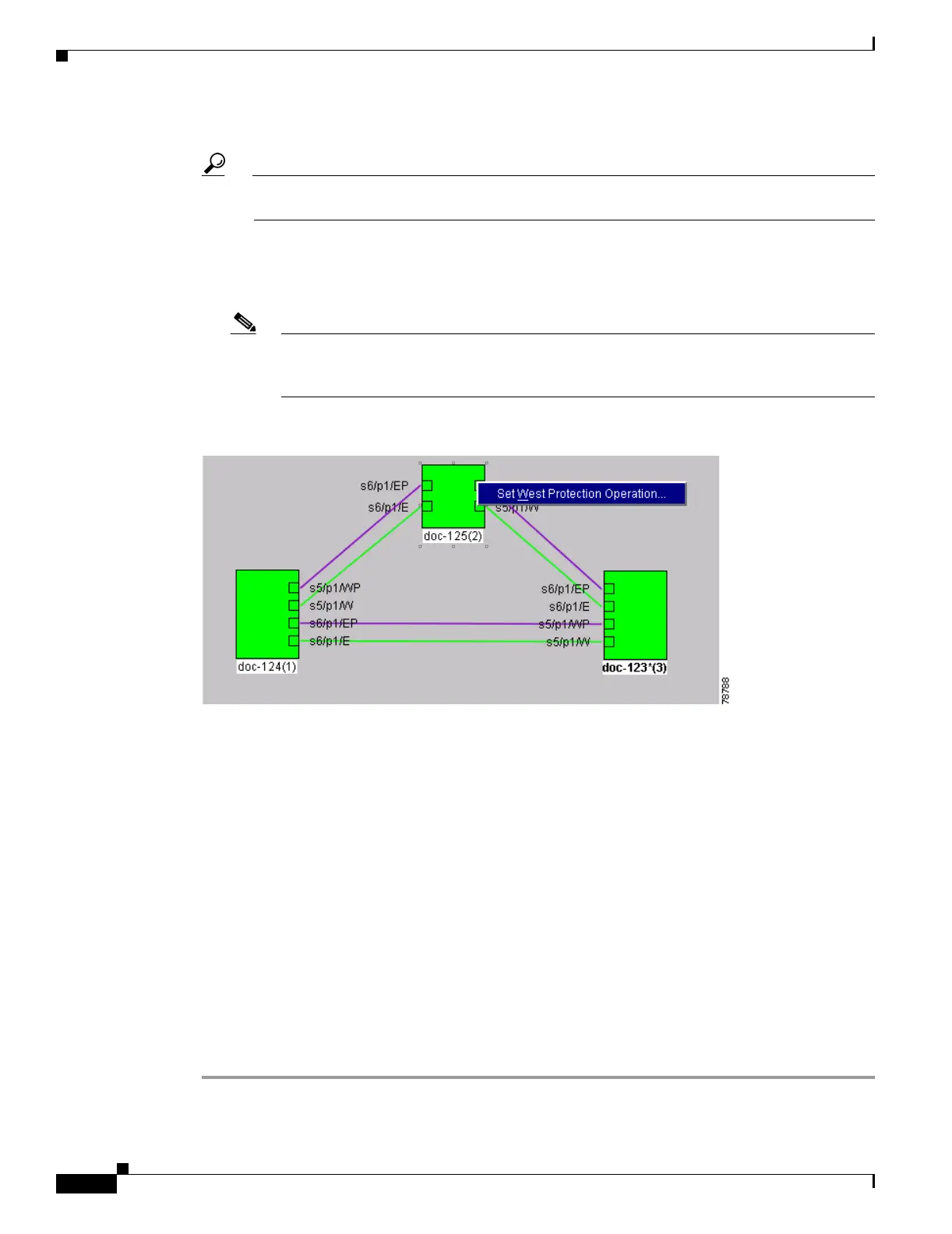
a. Right-click any BLSR node west channel (port) and choose Set West Protection Operation.
Figure 19-8 shows an example.
Note For two-fiber BLSRs, the squares on the node icons represent the BLSR working and protect
channels. You can right-click either channel. For four-fiber BLSRs, the squares represent
ports. You can right-click either working port.
Figure 19-8 Protection Operation on a Three-Node BLSR
b. In the Set West Protection Operation dialog box, choose LOCKOUT PROTECT SPAN from the
drop-down list. Click OK.
c. In the Confirm BLSR Operation dialog box, click Yes. An “L” appears on the selected channel (port)
where you created the lockout.
Lockouts generate LKOUTPR-S and FE-LOCKOUTOFPR-SPAN conditions.
Step 4 To lock out an east span:
a. Right-click the node’s east channel (port) and choose Set East Protection Operation.
b. In the Set East Protection Operation dialog box, choose LOCKOUT PROTECT SPAN from the
drop-down list. Click OK.
c. In the Confirm BLSR Operation dialog box, click Yes . An “L” indicating the lockout appears on the
selected channel (port) where you invoked the protection switch.
Lockouts generate LKOUTPR-S and FE-LOCKOUTOFPR-SPAN conditions.
Step 5 From the File menu, choose Close.
Step 6 Return to your originating procedure (NTP).

 Loading...


