22-27
Cisco ONS 15454 Procedure Guide, R5.0
October 2005
Chapter 22 DLPs A500 to A599
DLP-A530 Install the Tie-Down Bar
DLP-A530 Install the Tie-Down Bar
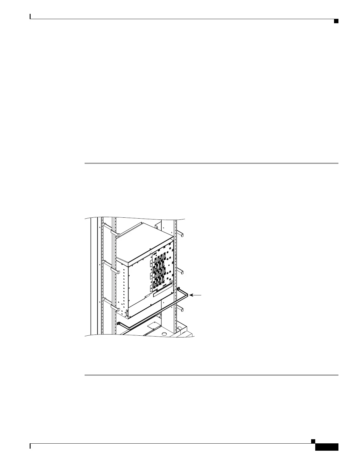
Step 1 Align the ends of the tie-down bar with the four screw holes located 1 rack unit (RU) below the
ONS 15454.
Figure 22-9 shows the tie-down bar, the ONS 15454, and the rack.
Figure 22-9 Tie-Down Bar
Step 2
Install the four screws into the rack.
Step 3 Return to your originating procedure (NTP).
Purpose This task installs the tie-down bar used to secure cabling on the rear of the
ONS 15454. The tie-down bar can be used to provide a diverse path for
redundant power feeds and cables.
Tools/Equipment Tie-down bar
Screws (4)
Prerequisite Procedures DLP-A5 Mount the Shelf Assembly in a Rack (One Person), page 17-5
DLP-A6 Mount the Shelf Assembly in a Rack (Two People), page 17-6
Required/As Needed As needed
Onsite/Remote Onsite
Security Level None
105012
Tie-down bar

 Loading...


