20-71
Cisco ONS 15454 Procedure Guide, R5.0
March 2005
Chapter 20 DLPs A300 to A399
DLP-A386 Install Electrical Cables on the UBIC-V EIAs
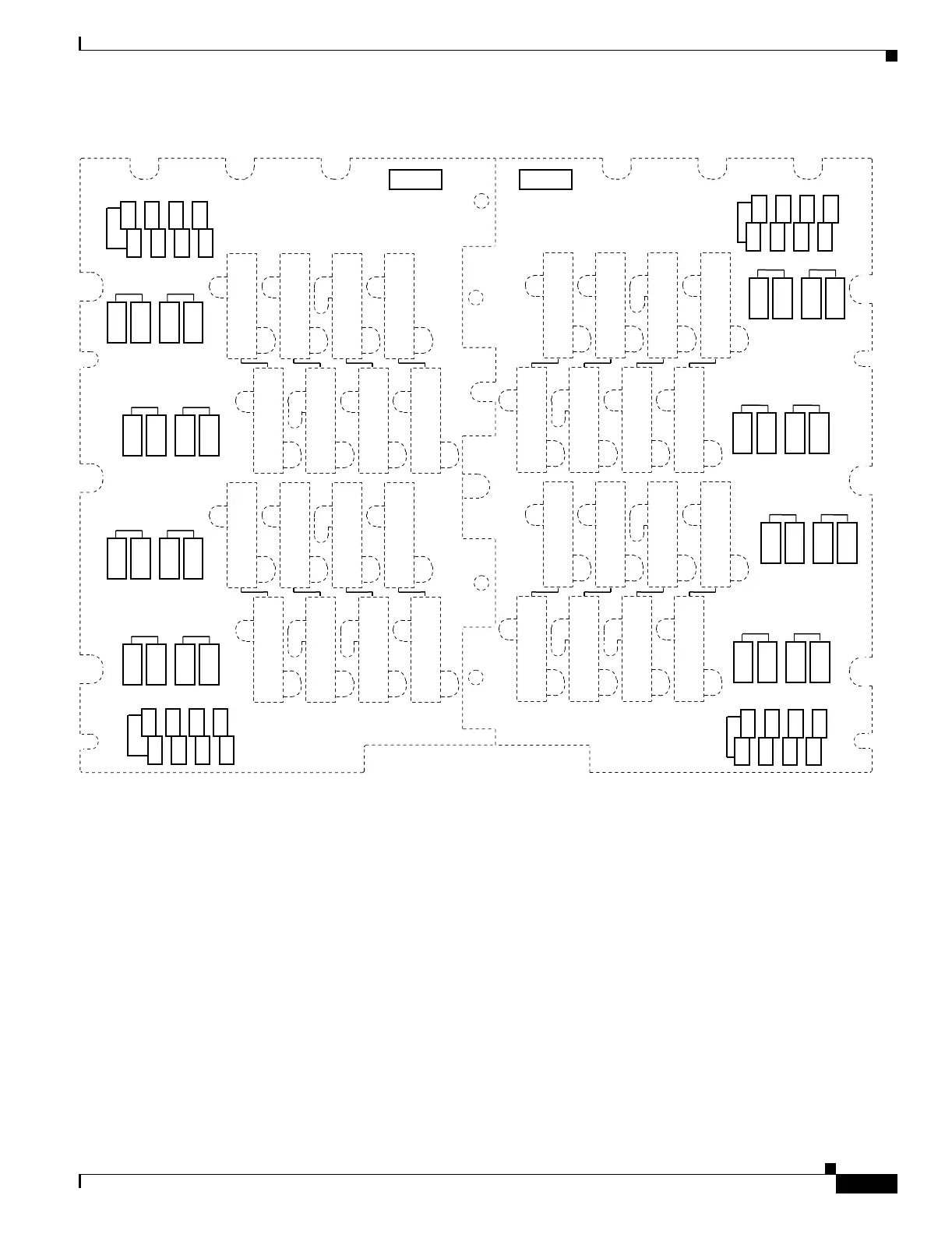
Figure 20-14 UBIC-V Slot Designations
Step 2
With the alignment slots of the cable connector aligned with the alignment standoffs of the UBIC
connector, carefully install the cable.
Step 3 Use the flat-head screwdriver to tighten the screw at the top left of the cable connector to 8 to 10 lbf-inch
(9.2 to 11.5kgf-cm). Repeat this for the screw at the bottom right of the connector. Alternate between
the two screws until both are tight.
Step 4 Repeat Steps 1 through 3 for each cable you want to install, moving from the bottom row to the top row.
If you are installing a cable near cables that are already installed, you might need to gently hold back the
surrounding cables. Make sure you install cables in pairs, Tx and Rx, each time.
Figure 20-15 shows a UBIC-V with cables installed in all connectors.
102176
B
DS1/DS3
Tx
Tx
Rx
Rx
HD(SLOT 17)
HD(SLOT 16)
DS3 37-48
DS1 43-56
DS3 1-12
DS1 1-14
DS3 1-12
DS1 1-14
DS3 25-36
DS1 29-42
HD(SLOT 17)
HD(SLOT 16)
DS3 37-48
DS1 43-56
DS3 1-12
DS1 1-14
DS3 1-12
DS1 1-14
DS3 25-36
DS1 29-42
HD(SLOT 16)
HD(SLOT 17)
DS3 37-48
DS1 43-56
DS3 13-24
DS1 15-28
DS3 13-24
DS1 15-28
DS3 25-36
DS1 29-42
HD(SLOT 16)
HD(SLOT 17)
DS3 37-48
DS1 43-56
DS3 13-24
DS1 15-28
DS3 13-24
DS1 15-28
DS3 25-36
DS1 29-42
JACKSCREW SHOULD BE
INSTALLED FIRST AND
REMOVED LAST
JACKSCREW SHOULD BE
INSTALLED FIRST AND
REMOVED LAST
JACKSCREW SHOULD BE
INSTALLED FIRST AND
REMOVED LAST
REAR COVER
BRACKET
LOCATION
REAR COVER
BRACKET
LOCATION
LD
DS3 1-12
DS1 1-14
DS3 1-12
DS1 1-14
DS3 1-12
DS1 1-14
(SLOT 14)(SLOT 13)(SLOT 12)
DS3 1-12
DS1 1-14
DS3 1-12
DS1 1-14
DS3 1-12
DS1 1-14
UNUSED
UNUSED
TX
RX
LD
DS3 1-12
DS1 1-14
DS3 1-12
DS1 1-14
(SLOT 17)(SLOT 16)(SLOT 15)
DS3 1-12
DS1 1-14
DS3 1-12
DS1 1-14
UNUSED
UNUSED
TX
RX
P
P
J17 J20 J21 J23
J25 J28 J29 J31
J24 J22 J19 J18
J32 J30 J27 J26
A
Tx
Tx
Rx
Rx
DS1/DS3
DS3 25-36
DS1 29-42
DS3 1-12
DS1 1-14
DS3 1-12
DS1 1-14
DS3 37-48
DS1 43-56
HD(SLOT 2)
HD(SLOT 1)
DS3 25-36
DS1 29-42
DS3 1-12
DS1 1-14
DS3 1-12
DS1 1-14
DS3 37-48
DS1 43-56
HD(SLOT 1)
HD(SLOT 2)
DS3 25-36
DS1 29-42
DS3 13-24
DS1 15-28
DS3 13-24
DS1 15-28
DS3 37-48
DS1 43-56
HD(SLOT 1)
HD(SLOT 2)
DS3 25-36
DS1 29-42
DS3 13-24
DS1 15-28
DS3 13-24
DS1 15-28
DS3 37-48
DS1 43-56
JACKSCREW SHOULD BE
INSTALLED FIRST AND
REMOVED LAST
REAR COVER
BRACKET
LOCATION
JACKSCREW SHOULD BE
INSTALLED FIRST AND
REMOVED LAST
JACKSCREW SHOULD BE
INSTALLED FIRST AND
REMOVED LAST
REAR COVER
BRACKET
LOCATION
HD(SLOT 1)
HD(SLOT 2)
LD
DS3 1-12
DS1 1-14
DS3 1-12
DS1 1-14
DS3 1-12
DS1 1-14
(SLOT 6) (SLOT 5) (SLOT 4)
DS3 1-12
DS1 1-14
DS3 1-12
DS1 1-14
DS3 1-12
DS1 1-14
UNUSED
UNUSED
TX
RX
LD
DS3 1-12
DS1 1-14
DS3 1-12
DS1 1-14
(SLOT 3) (SLOT 2) (SLOT 1)
DS3 1-12
DS1 1-14
DS3 1-12
DS1 1-14
UNUSED
UNUSED
P
P
TX
RX
J7 J5 J4 J1
J15 J13 J12 J9
J2 J3 J6 J8
J10 J11 J14 J16

 Loading...


