17-53
Cisco ONS 15454 Procedure Guide, R5.0
March 2005
Chapter 17 DLPs A1 to A99
DLP-A44 Install Fiber-Optic Cables for BLSR Configurations
Note To avoid error, connect fiber-optic cable so that the farthest slot to the right represents the east port, and
the farthest slot to the left represents the west port. Fiber connected to an east port at one node must plug
into the west port on an adjacent node.
Caution Do not provision the BLSR east and west ports on the same OC-N card.
Step 1 Plan your fiber connections. Use the same plan for all BLSR nodes.
Step 2 Plug the fiber into the Tx connector of an OC-N card at one node and plug the other end into the Rx
connector of an OC-N card at the adjacent node. The card displays an SF LED if the transmit and receive
fibers are mismatched.
Note Do not mix working and protect card connections when connecting a four-fiber BLSR. The
BLSR does not function if working and protect cards are interconnected. See Figure 17-24 on
page 17-54 for an example of correct four-fiber BLSR cabling.
Step 3 Repeat Step 2 until you have configured the ring.
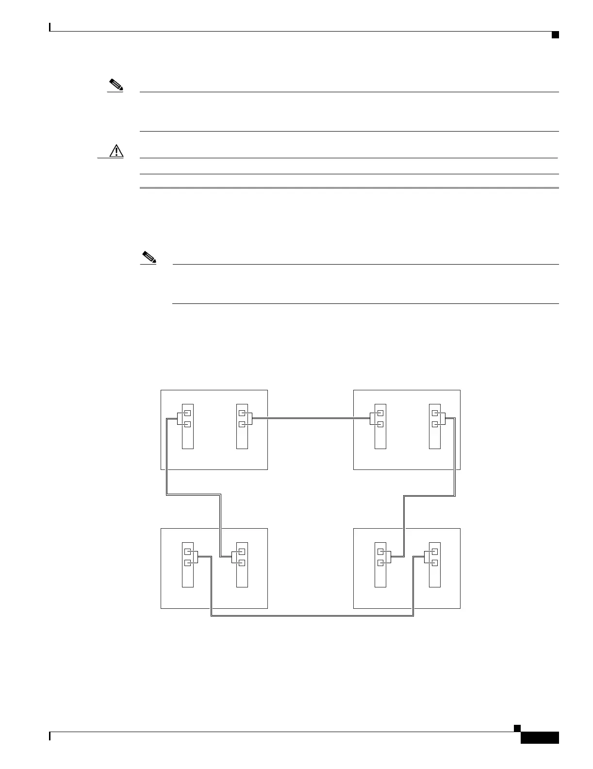
Figure 17-23 shows fiber connections for a two-fiber BLSR with trunk (span) cards in Slot 5 (west) and
Slot 12 (east).
Figure 17-23 Connecting Fiber to a Four-Node, Two-Fiber BLSR
Figure 17-24 shows fiber connections for a four-fiber BLSR. Slot 5 (west) and Slot 12 (east) carry the
working traffic. Slot 6 (west) and Slot 13 (east) carry the protect traffic.
55297
Node 1
West East
West East
West East
West East
Slot 5
Tx
Rx
Slot 12
Tx
Rx
Node 4
Slot 5
Tx
Rx
Slot 12
Tx
Rx
Node 2
Slot 5
Tx
Rx
Slot 12
Tx
Rx
Node 3
Slot 5
Tx
Rx
Slot 12
Tx
Rx

 Loading...


