6-21
Cisco ONS 15454 Procedure Guide, R5.0
August 2005
Chapter 6 Create Circuits and VT Tunnels
NTP-A184 Create an Automatically Routed DS-3 Circuit
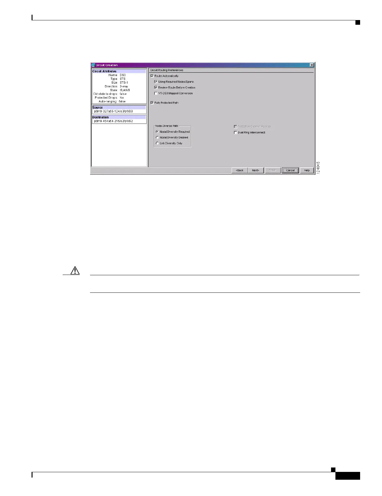
Figure 6-5 Setting Circuit Routing Preferences for a DS-3 Circuit
Step 12
To set the circuit path protection, complete one of the following:
• To route the circuit on a protected path, leave Fully Protected Path checked and continue with
Step 13. CTC creates a fully protected circuit route based on the path diversity option you choose.
Fully protected paths might or might not have path protection path segments (with primary and
alternate paths), and the path diversity options apply only to path protection path segments, if any
exist.
• To create an unprotected circuit, uncheck Fully Protected Path and continue with Step 16.
• To route the circuit on a BLSR protection channel, if available, uncheck Fully Protected Path,
check Protection Channel Access, click Yes in the Warning dialog box, then continue with Step 16.
Caution Circuits routed on BLSR protection channels are not protected and are preempted during BLSR
switches.
Step 13 If you selected Fully Protected Path in Step 12 and the circuit will be routed on a path protection, choose
one of the following:
• Nodal Diversity Required—Ensures that the primary and alternate paths within path protection
portions of the complete circuit path are nodally diverse.
• Nodal Diversity Desired—Specifies that node diversity is preferred, but if node diversity is not
possible, CTC creates fiber-diverse paths for the path protection portion of the complete circuit path.
• Link Diversity Only—Specifies that only fiber-diverse primary and alternate paths for path
protection portions of the complete circuit path are needed. The paths might be node-diverse, but
CTC does not check for node diversity.
Step 14 If you selected Fully Protected Path in Step 12 and the circuit will be routed on a path protection DRI,
check the Dual Ring Interconnect check box.
Step 15 If you selected VT-DS3 Mapped Conversion in Step 11, complete the following substeps; otherwise,
continue with Step 16:
a. Click Next.
b. In the Conversion Circuit Route Constraints area, complete the following:
• Node—Choose a node with a DS3XM-12 card installed.

 Loading...


