14-7
Cisco ONS 15454 Procedure Guide, R5.0
December 2004
Chapter 14 Add and Remove Nodes
NTP-A240 Remove a BLSR Node
b. Click the Provisioning > BLSR tabs.
c. Choose the desired BLSR, then click Edit.
d. In the BLSR window, verify that all the port information is visible. If not, press Ctrl and drag the
node icons to a new location so the information can be viewed.
e. Complete the “DLP-A515 Print CTC Data” task on page 22-5.
f. Close the BLSR window by choosing Close from the File menu.
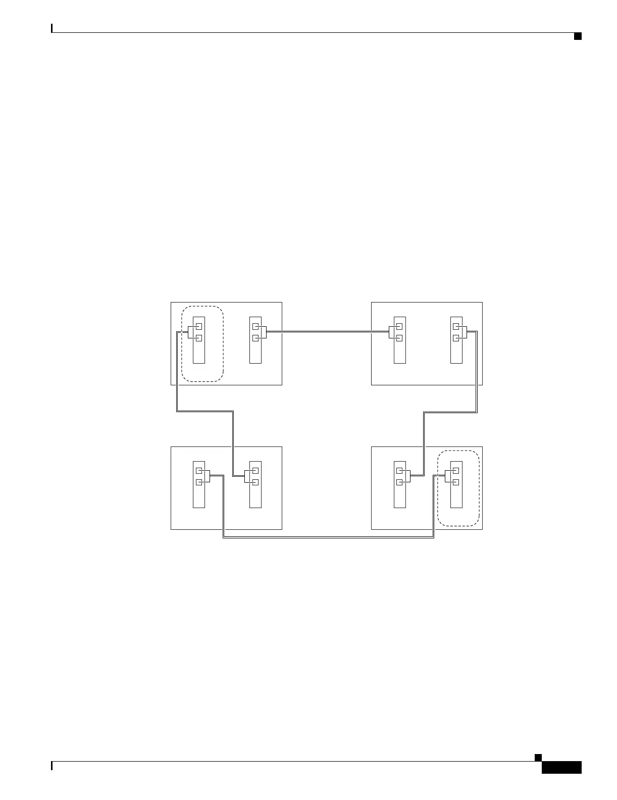
Step 5 Referring to the BLSR diagram, identify the following:
• The node that is connected through its west port to the target (removal) node. For example, if you
were removing Node 4 in Figure 14-3, Node 1 is the node connected through its west port to Node 4.
• The node that is connected through its east port to the target (removal) node. In Figure 14-3, Node 3
is the node connected through its east port to Node 4.
Write down the slot and port of the BLSR ring in the node.
Figure 14-3 Four-Node, Two-Fiber BLSR Before a Node Is Removed
Step 6
Complete the “DLP-A298 Check the Network for Alarms and Conditions” task on page 19-63 to verify
that the BLSR is free of alarms. If trouble is indicated (for example, a major alarm exists), resolve the
problem before proceeding. See Chapter 7, “Manage Alarms” or, if necessary, refer to the
Cisco ONS 15454 Troubleshooting Guide.
Step 7 From the View menu, choose Go to Other Node. Choose the node that you will remove and click OK.
Step 8 Click the Circuits tab. If the Scope setting is set to Network, choose Node from the Scope drop-down
list. Make sure that the Filter button is off (not indented) to ensure that all circuits are visible.
Step 9 Delete all circuits that originate or terminate on the node. See the “DLP-A333 Delete Circuits” task on
page 20-21.
78791
West East
West East
West East
West East
Slot 5
Tx
Rx
Slot 12
Tx
Rx
Node 4 (to be removed)
Slot 5
Tx
Rx
Slot 12
Tx
Rx
Node 2Node 1
Slot 5
Tx
Rx
Slot 12
Tx
Rx
Node 3
Slot 5
Tx
Rx
Slot 12
Tx
Rx

 Loading...


