14-3
Cisco ONS 15454 Procedure Guide, R5.0
December 2004
Chapter 14 Add and Remove Nodes
NTP-A212 Add a BLSR Node
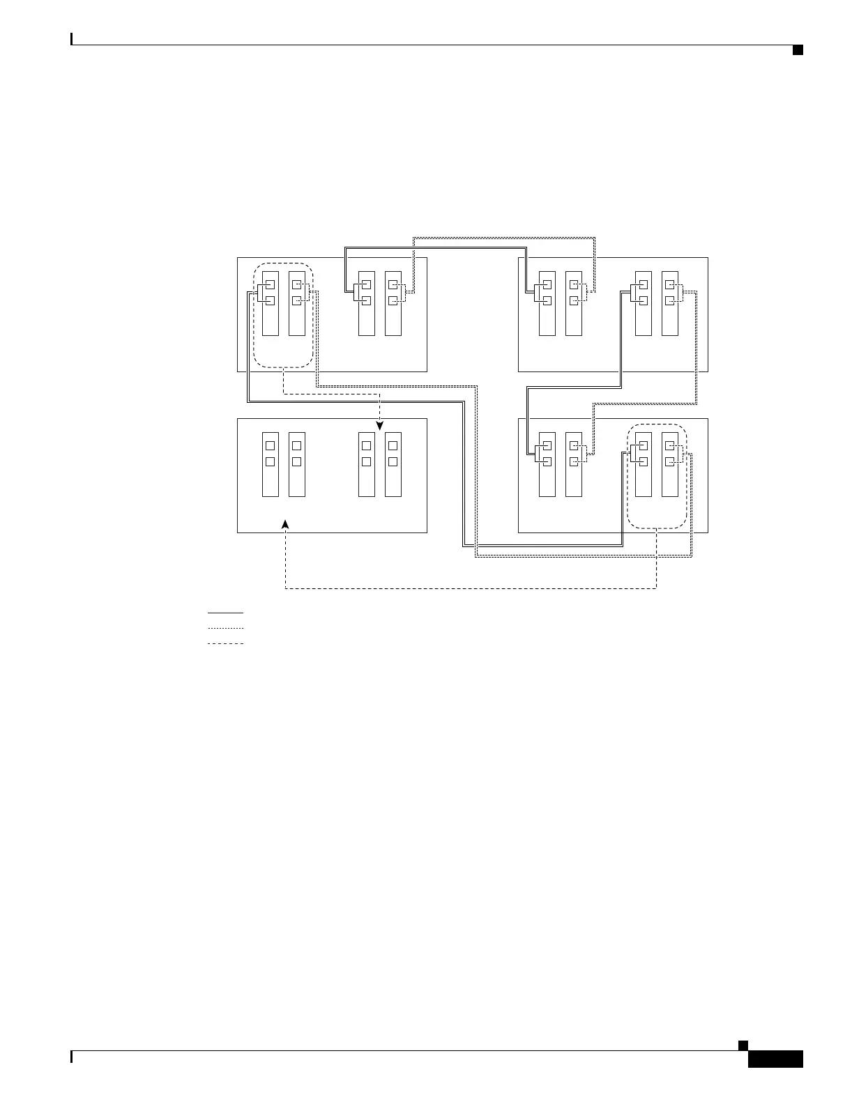
Figure 14-2 shows a sample drawing of a three-node, four-fiber BLSR. The dashed arrow shows the new
fiber connections that will be made to add the fourth node. For four-fiber BLSRs, two fiber sets will be
reconnected, the working fiber and the protect fiber.
Figure 14-2 Three-Node, Four-Fiber BLSR Before a Fourth Node is Added
Step 2 According to local site practice, complete the “NTP-A108 Back Up the Database” procedure on
page 15-4 for all the nodes in the ring.
Step 3 Verify the card installation on the new node using the “NTP-A24 Verify Card Installation” procedure on
page 4-2. Verify that the OC-N cards that will be the BLSR trunk cards match the BLSR optical rate. For
example, if the BLSR is OC-48, the new node must have OC-48 cards installed. If the OC-N cards are
not installed or the optical rates do not match the BLSR, complete the “NTP-A16 Install the OC-N
Cards” procedure on page 2-6.
Step 4 Verify that fiber is available to connect the new node to the existing nodes. Refer to the diagram drawn
in Step 1.
Step 5 Complete the “NTP-A35 Verify Node Turn-Up” procedure on page 5-2. In order to have CTC visibility
to the new node after it is added, you must be an authorized user on the node and you must have IP
connectivity to the node.
Step 6 Create a static route on the new node if the following conditions are present. If the conditions are not
present, continue with Step 7.
• The IP address for the new node is on the same subnet as other nodes in the network.
• On the new node Provisioning > Network > General subtab, Craft Access Only is not checked under
Gateway Settings.
78741
Node 1
West East
West East
West East
West East
Slot
5
Slot
12
New Node
Slot
5
Slot
12
Node 2
Slot
5
Slot
12
Node 3
Slot
5
Slot
12
Tx
Rx
Slot
6
Slot
13
Tx
Rx
Slot
6
Slot
13
Tx
Rx
Slot
6
Slot
13
Tx
Rx
Slot
6
Slot
13
Working fibers
Protect fibers
New fiber connections

 Loading...


