1-12
Cisco ONS 15454 Procedure Guide, R5.0
March 2005
Chapter 1 Install the Shelf and Backplane Cable
NTP-A119 Install the Alarm Expansion Panel
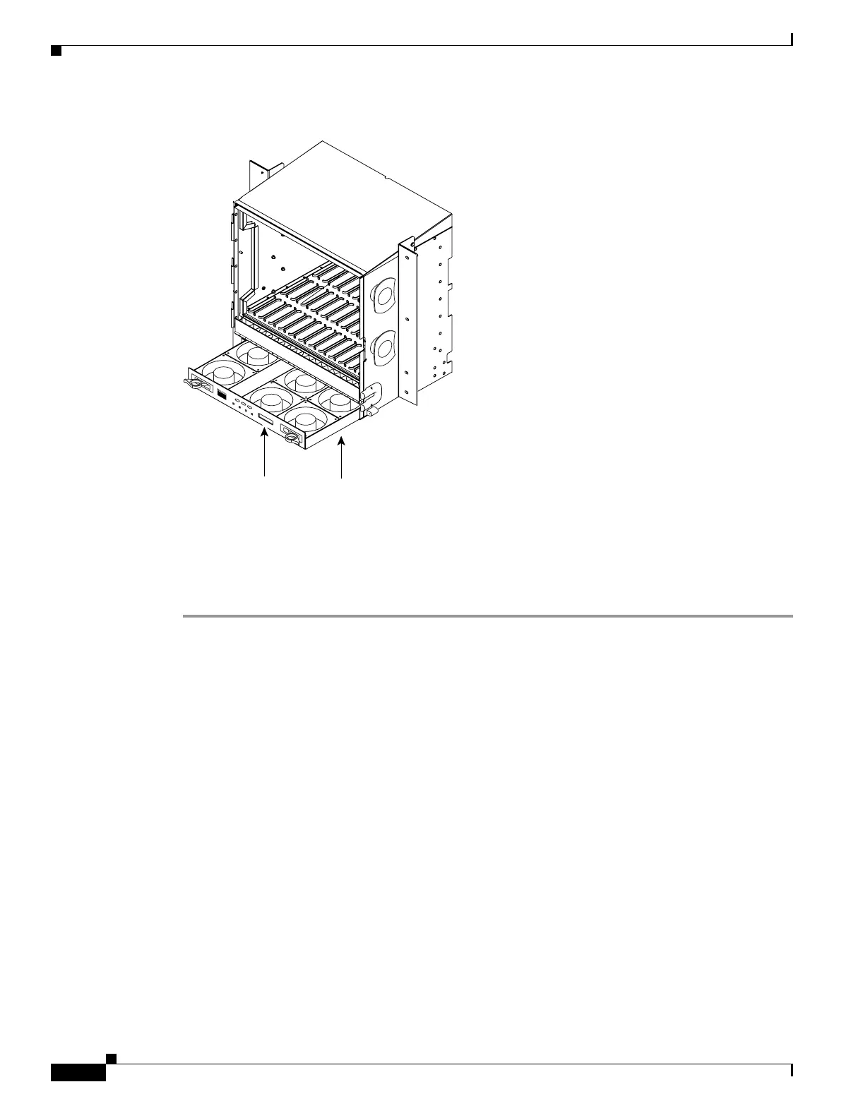
Figure 1-1 Installing the Fan-Tray Assembly
Step 4 Continue with the “NTP-A119 Install the Alarm Expansion Panel” procedure on page 1-12 if you plan
to install an alarm expansion panel (AEP). If not, continue with the “NTP-A8 Attach Wires to Alarm,
Timing, LAN, and Craft Pin Connections” procedure on page 1-15.
Stop. You have completed this procedure.
NTP-A119 Install the Alarm Expansion Panel
FAN FA IL
CRIT
MAJ
M
IN
38532
Fan tray
assembly
LCD
Purpose This procedure installs an alarm expansion panel (AEP) onto the
15454-SA-ANSI or 15454-SA-HD shelf backplane. The AEP provides
alarm contacts in addition to the 16 provided by the AIC-I card. Typically,
the AEP is preinstalled when ordered with the ONS 15454; however, the
AEP can be ordered separately. The AIC-I card must be installed before
you can provision the alarm contacts enabled by the AEP.
Tools/Equipment #2 Phillips screwdriver
Medium slot-head screwdriver
Small slot-head screwdriver
Wire wrapper
6-pair #29 AWG double-shielded cable
Standoffs (4)
Prerequisite Procedures DLP-A10 Remove the Lower Backplane Cover, page 17-10
Required/As Needed As needed

 Loading...


