1-14
Cisco ONS 15454 Procedure Guide, R5.0
March 2005
Chapter 1 Install the Shelf and Backplane Cable
NTP-A119 Install the Alarm Expansion Panel
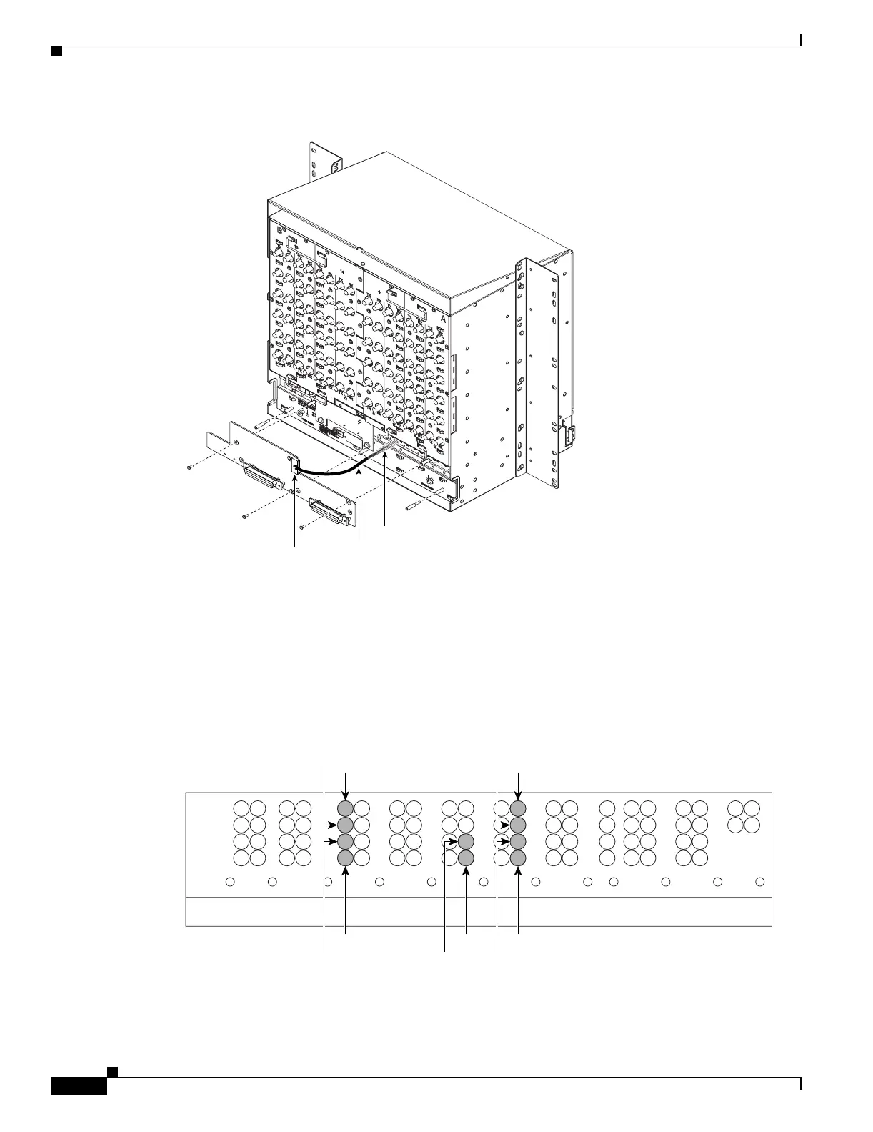
Figure 1-3 Installing Standoffs and the AEP
Step 4
Insert and tighten three screws to secure the AEP to the backplane.
Step 5 Connect the AEP cable to the backplane and AEP:
a. Connect the 10 colored wires to the wire-wrap pins on the backplane. Figure 1-4 shows where the
cable wires are connected. Table 1-1 shows AEP and AIC-I signals that each wire carries.
b. Plug the other end of the AEP cable into AEP connector port. The brown pin is on the top.
Figure 1-4 AEP Wire-Wrap Connections to Backplane Pins
78403
AEP cable
Connector
Wires
1
2
3
4
A
FG4FG3FG2FG1
BITS LAN
1
2
3
4
AB
1
2
3
4
AB
IN
1
2
3
4
AB
IN/OUT
FG6FG5
7
8
95
106
ABAB
ENVIRONMENTAL ALARMS
IN
ACO
FG7
1
2
3
4
IN
AB
FG8
1
2
3
4
AB
MODEM
FG9
1
2
3
4
A
CRAFT
AUDVIS
FG10
1
2
3
4
AB
LOCAL ALARMS
IN
FG12FG11
11
12
ABB
96618
White
Black
Blue
Green
Slate
Violet
Orange
Yellow
Red
Brown

 Loading...


