17-25
Cisco ONS 15454 Procedure Guide, R5.0
March 2005
Chapter 17 DLPs A1 to A99
DLP-A20 Install Timing Wires on the Backplane
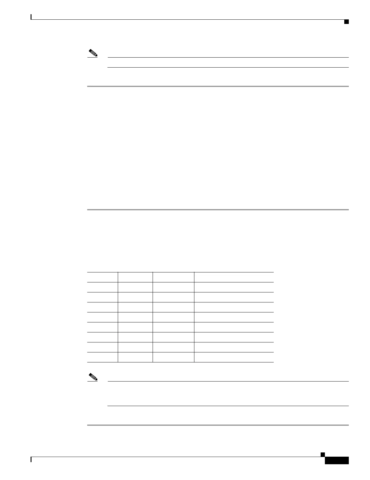
Note The X.25, Modem, and TBOS pin fields are not active on either pin field.
Step 2 Return to your originating procedure (NTP).
DLP-A20 Install Timing Wires on the Backplane
Step 1 Using 100-ohm shielded BITS clock cable pair #22 or #24 AWG (0.51 mm² or 0.64 mm²), twisted-pair
T1-type, wrap the clock wires on the appropriate wire-wrap pins according to local site practice.
Ground the shield of the BITS input cable at the BITS end. For BITS output, wrap the ground shield of
the BITS cable to the frame ground pin (FG1) located beneath the column of BITS pins. Table 17-1 lists
the pin assignments for the BITS timing pin fields.
Note For more detailed information about timing, refer to the “Security and Timing” chapter of the
Cisco ONS 15454 Reference Manual. To set up system timing, see the “NTP-A28 Set Up
Timing” procedure on page 4-9.
Step 2 Return to your originating procedure (NTP).
Purpose This task installs the BITS timing wires on the backplane.
Tools/Equipment Wire wrapper
100-ohm shielded BITS clock cable pair #22 or #24 AWG (0.51 mm² or
0.64 mm²), twisted-pair T1-type
Prerequisite Procedures None
Required/As Needed As needed
Onsite/Remote Onsite
Security Level None
Table 17-1 External Timing Pin Assignments for BITS
BITS Pin Tip/Ring CTC/TL1 Name Function
A4 Ring BITS-1 Input from BITS device 1
B4 Tip BITS-1 Input from BITS device 1
A3 Ring BITS-1 Output to external device 1
B3 Tip BITS-1 Output to external device 1
A2 Ring BITS-2 Input from BITS device 2
B2 Tip BITS-2 Input from BITS device 2
A1 Ring BITS-2 Output to external device 2
B1 Tip BITS-2 Output to external device 2

 Loading...


