1-20
Cisco ONS 15454 Procedure Guide, R5.0
March 2005
Chapter 1 Install the Shelf and Backplane Cable
NTP-A120 Install an External Wire-Wrap Panel to the AEP
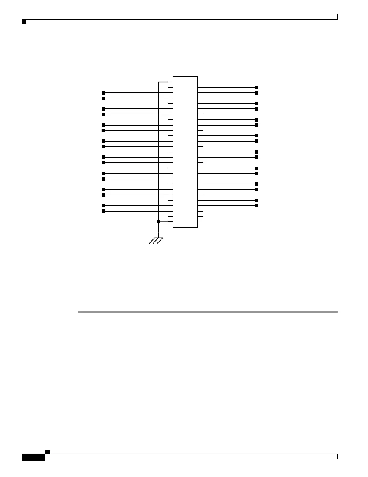
Figure 1-7 Alarm Output Connector
Step 4
Complete one of the following:
• If you plan to install electrical cards, continue with the “NTP-A9 Install the Electrical Card Cables
on the Backplane” procedure on page 1-21.
• If you do not plan to install electrical cards, continue with the “NTP-A11 Install the Rear Cover”
procedure on page 1-22.
Stop. You have completed this procedure.
NO_5
XREF=7
COM_5
XREF=7
NO_3
XREF=7
COM_3
XREF=7
COM_14
XREF=7
NO_14
XREF=7
XREF=7
COM_12
NO_12
XREF=7
COM_10
XREF=7
NO_10
XREF=7
COM_8
XREF=7
NO_8
XREF=7
COM_6
XREF=7
NO_6
XREF=7
COM_4
XREF=7
NO_4
XREF=7
COM_2
XREF=7
NO_1
XREF=7
NO_2
XREF=7
COM_0
XREF=7
NO_0
XREF=7
NO_15
XREF=7
COM_15
XREF=7
NO_13
XREF=7
COM_13
XREF=7
COM_1
XREF=7
NO_11
XREF=7
COM_11
XREF=7
NO_9
XREF=7
COM_9
XREF=7
NO_7
XREF=7
COM_7
XREF=7
Connector
Alarm Output
GND1
GND2
1
10
11
12
13
14
15
16
17
18
19
2
20
21
22
23
24
25
26
27
28
29
3
30
31
32
33
34
35
36
37
38
39
4
40
41
42
43
44
45
46
47
48
49
5
50
6
7
8
9
51
52
P4
79876

 Loading...


