15-35
Cisco ONS 15454 Procedure Guide, R5.0
December 2004
Chapter 15 Maintain the Node
NTP-A266 Edit Network Element Defaults
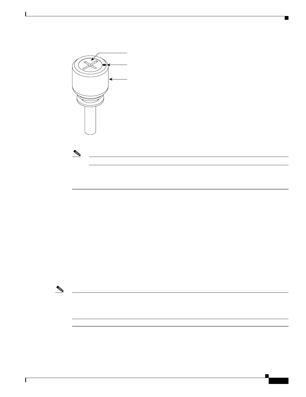
Figure 15-14 UBIC-V EIA Jack Screw
Step 4
Grip two of the jack screws and use them to carefully pull the UBIC-V away from the shelf.
Note Attach backplane sheet metal covers whenever EIAs are not installed.
Step 5 Perform the “DLP-A190 Install a UBIC-V EIA” task on page 18-61 to install the new UBIC-V EIA.
Stop. You have completed this procedure.
NTP-A266 Edit Network Element Defaults
Note For a list of card and node default settings, refer to the “Network Element Defaults” appendix in the
Cisco ONS 15454 Reference Manual. To change card settings individually (that is, without changing the
defaults), see Chapter 11, “Change Card Settings.” To change node settings, see Chapter 10, “Change
Node Settings.”
Step 1 Complete the “DLP-A60 Log into CTC” task on page 17-66 at the node where you want to edit NE
defaults.
Step 2 Click the Provisioning > Defaults Editor tabs.
115260
Thumbscrew
Inner screw
Rotation indicator
Purpose This procedure edits the NE defaults using the NE Defaults Editor. The
new defaults can either be applied only to the node on which they are edited
or exported to a file and imported for use on other nodes.
Tools/Equipment None
Prerequisite Procedures None
Required/As Needed As needed
Onsite/Remote Onsite or remote
Security Level Superuser

 Loading...


