AKD User Guide |
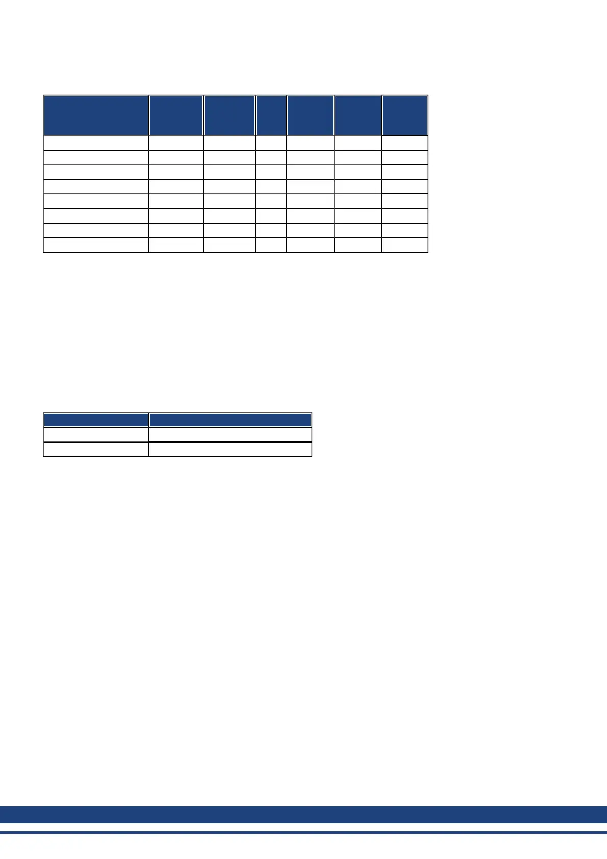
States of the status machine
State Bit 6
switch on
disabled
Bit 5
quick stop
Bit 3
fault
Bit 2
operation
enabled
Bit 1
switched
on
Bit 0
ready to
switch on
Not ready to switch on 0 X 0 0 0 0
Switch on disabled 1 X 0 0 0 0
Ready to switch on 0 1 0 0 0 1
Switched on 0 1 0 0 1 1
Operation enabled 0 1 0 1 1 1
Fault 0 X 1 0 0 0
Fault reaction active 0 X 1 1 1 1
Quick stop active 0 0 0 1 1 1
Bits marked by X are irrelevant
Description of the remaining bits in the status word
Bit 4: voltage_enabled The DC-link voltage is present if this bit is set.
Bit 7: warning There are several possible reasons for Bit 7 being set and this warning being produced. The rea-
son of a warning can be seen by the Error code of the Emergency message, which is sent on the bus caused by
this warning.
Bit 9: remoteis always set to1, i.e. thedrivecan always communicateandbeinfluencedviatheRS232-interface.
Bit 10: target_reached This is set when the drive has reached the target position.
Bit 11: internal_limit_active This bit specifies that a movement was or is limited. In different modes, different
warnings cause the bit to be set. The following assignments exist:
Mode of operation Warnings which set Bit 11
all n04, n06, n07, n10, n11, n14
0x1 (PP), 0x88 n03, n08, n09, n20
93 Kollmorgen | December 2010
 Loading...


