AKD User Guide |
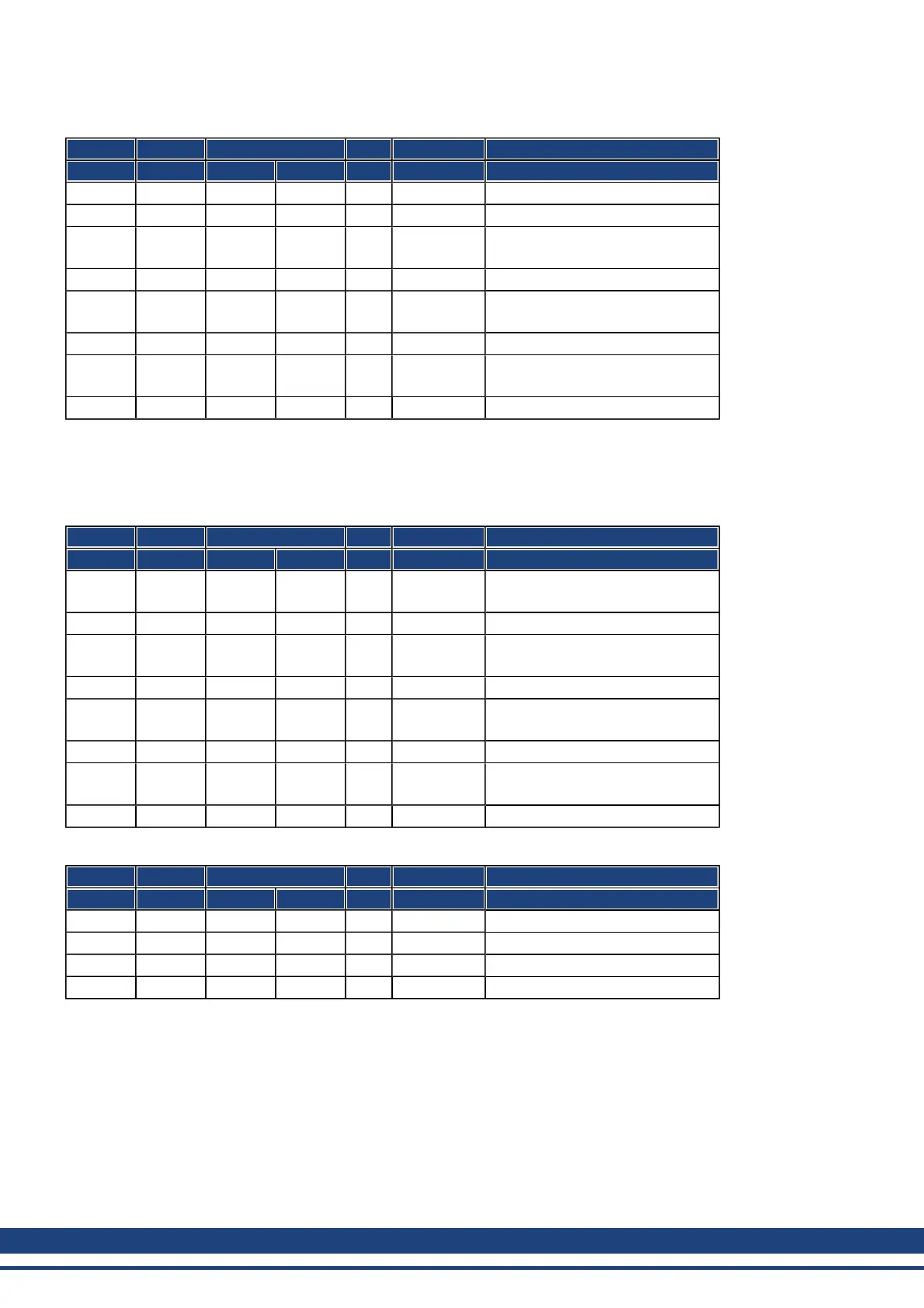
Mapping configuration for axis 1:
COB-ID Control Index Sub- Data Comment
byte Low byte High byte index
601 2F 01 1A 00h 00 00 00 00 TPDO2: delete mapping
581 60 01 1A 00h 00 00 00 00
601 23 01 1A 01h 20 00 63 60 TPDO2, entry 1:
actual position in increments
581 60 01 1A 01h 00 00 00 00
601 23 01 1A 02h 20 00 02 10 TPDO2, entry 2:
Dummy entry 4 bytes
581 60 01 1A 02h 00 00 00 00
601 2F 01 1A 00h 02 00 00 00 TPDO2, enter number of
mapped objects
581 60 01 1A 00h 00 00 00 00
The same must be done for axis 2.
Hereit is assumed that bothdrives accept new trajectory values with every SYNC command, andmust returntheir
incrementalpositionandmanufacturerstatus values. Thecommunicationparameters must beset accordingly.
Axis 1:
COB-ID Control Index Sub- Data Comment
byte Low byte High byte index
601 2F 01 14 02h 01 00 00 00 RPDO2 axis 1, reaction on every
sync
581 60 01 14 02h 00 00 00 00
602 2F 01 14 02h 01 00 00 00 RPDO2 axis 2, reaction on every
sync
582 60 01 14 02h 00 00 00 00
601 2F 01 18 02h 01 00 00 00 TPDO2 axis 1, reaction on every
sync
581 60 01 18 02h 00 00 00 00
602 2F 01 18 02h 01 00 00 00 TPDO2 axis 2, reaction on every
sync
582 60 01 18 02h 00 00 00 00
The other Tx-PDOs 3 and 4 should be switched off to minimize bus-load:
COB-ID Control Index Sub- Data Comment
byte Low byte High byte index
601 23 02 18 01h 81 03 00 80 Switch off TPDO3
581 60 02 18 01h 00 00 00 00
601 23 03 18 01h 81 04 00 80 Switch off TPDO4
581 60 03 18 01h 00 00 00 00
The same must be done for axis 2.
147 Kollmorgen | December 2010
 Loading...


