For a detailed description of the mounting, disassembly and electrical connec-
tion of the module, please refer to the System Assembly, Construction and Con-
nection chapter
Ä
Chapter 2.6 “AC500 (Standard)” on page 1248.
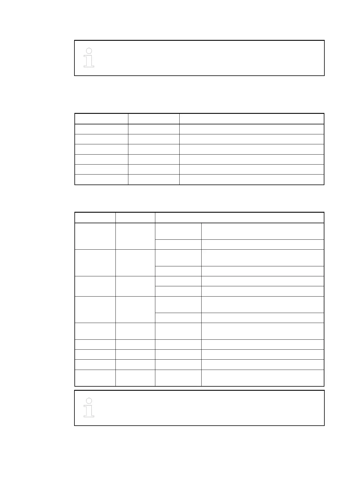
The terminals 1.0, 2.0 and 3.0 as well as 1.1, 2.1 and 3.1 are electrically interconnected within
the terminal unit and have always the same assignment, independent of the inserted module:
Table 186: Assignment of the terminals
Terminal Signal Description
1.0 UP Process voltage UP (+24 VDC)
1.1 ZP Process voltage ZP (0 VDC)
2.0 UP Process voltage UP (+24 VDC)
2.1 ZP Process voltage ZP (0 VDC)
3.0 UP Process voltage UP (+24 VDC)
3.1 ZP Process voltage ZP (0 VDC)
Table 187: Assignment of the terminals of removable connectors X11 and X12 (Serial inter-
faces)
Terminal Signal Description
1 Term-P RS-485 Internal line terminating resistor for non-
inverted signal (Rx/Tx-P)
RS-422 Non-inverted receive signal terminal (RxD+)
2 Rx/Tx-P RS-485 Non-inverted I/O signal terminal for each
channel
RS-422 Non-inverted transmit signal terminal (TxD+)
3 Rx/Tx-N RS-485 Inverted I/O signal terminal for each channel
RS-422 Inverted transmit signal terminal (TxD-)
4 Term-N RS-485 Internal line-terminating-resistor for inverted
signal (Rx/Tx-N) terminal
RS-422 Inverted receive signal terminal (RxD-)
5 RTS RS-232 Request To Send signal terminal for each
channel
6 TxD RS-232 Transmit signal terminal for each channel
7 SGND RS-232 Signal ground for each channel
8 RxD RS-232 Receive signal terminal for each channel
9 CTS RS-232 Clear To Send signal terminal for each
channel
The connection of SGND (ground) is optional for RS-485/RS-422.
Communication Interface Modules (S500) > PROFINET
2019/04/17 3ADR010121, 13, en_US 1087