Home
ABB
Control Unit
AC500 PLC
Page 1258
ABB AC500 PLC - Page 1258
1315 pages
Manual
Save Page as PDF
To Next Page
To Next Page
To Previous Page
To Previous Page
Loading...
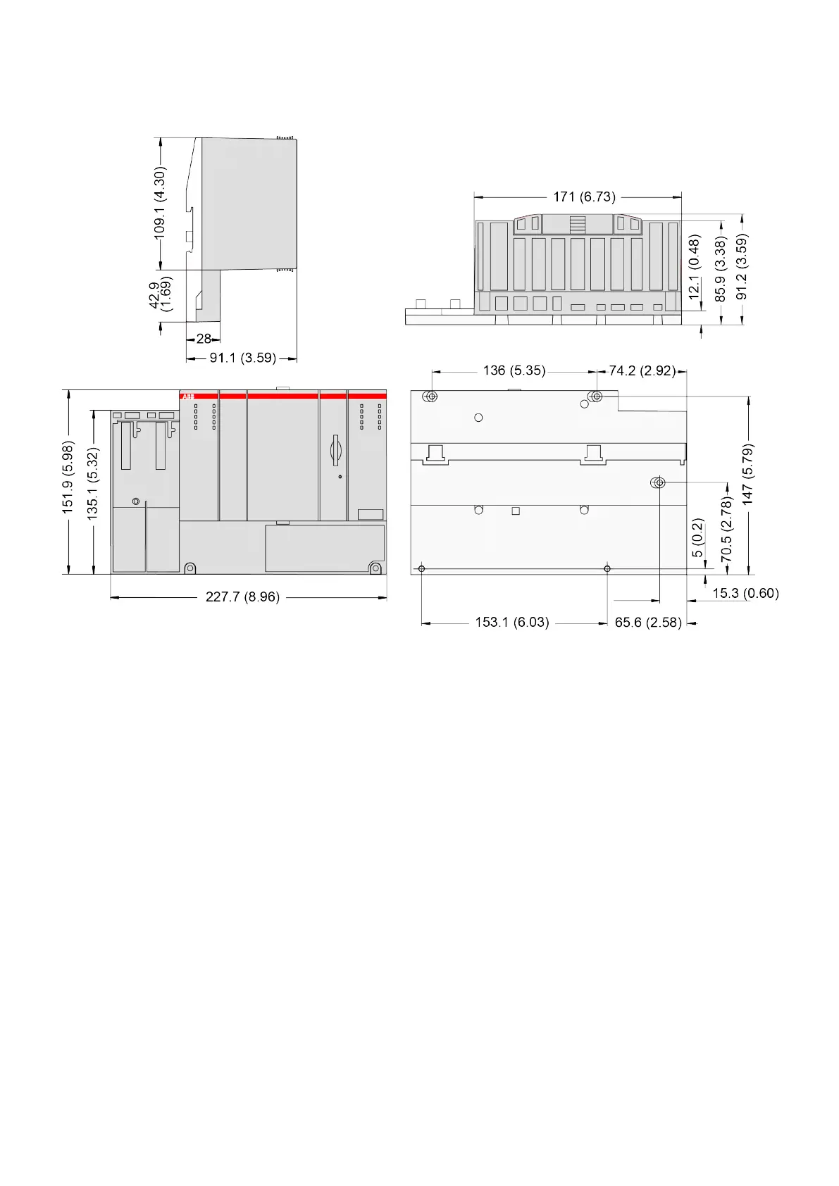
Fig. 219: Processor Module PM595, side view
, top view
, front view
, back view
Dimensions:
PM595
System Assembly
, Construction and Connection
AC500 (Standard) > Mechanical Dimensions
2019/04/17
3ADR010121, 13, en_US
1258
1257
1259
Table of Contents
Main Page
Table of contents
2
1 Device Specifications
4
1.1 Terminal Bases (AC500 Standard)
4
1.1.1 TB51x-TB54x
4
1.1.1.1 Short Description
5
1.1.1.2 Connections
7
1.1.1.2.1 I/O Bus
7
1.1.1.2.2 Power Supply
7
1.1.1.2.3 Serial Interfaces COM1/COM2
8
1.1.1.2.4 ARCNET Network Interface
9
1.1.1.2.5 Ethernet Networking Interfaces
9
1.1.1.2.6 Neutral FieldBusPlug Interface
10
1.1.1.3 Technical Data
11
1.1.1.4 Ordering Data
12
1.1.2 TF501-CMS and TF521-CMS - Function Module Terminal Bases
13
1.1.2.1 Description
14
1.1.2.2 Electrical Connection
15
1.1.2.2.1 Serial Interface COM1
17
1.1.2.2.2 Ethernet Networking Interface
18
1.1.2.3 Technical Data
19
1.1.2.4 Ordering Data
20
1.2 Processor Modules
20
1.2.1 AC500-eCo
21
1.2.1.1 PM55x-xP and PM56x-xP
21
1.2.1.1.1 Short Description
23
1.2.1.1.2 Assortment
23
1.2.1.1.3 Connections
24
1.2.1.1.4 Power Supply
27
1.2.1.1.5 Onboard I/Os
28
1.2.1.1.6 Diagnosis
30
1.2.1.1.7 State LEDs and Operating Elements
30
1.2.1.1.8 Technical Data
32
1.2.1.1.9 Ordering Data
36
1.2.1.2 Onboard I/Os in Processor Module PM55x
37
1.2.1.2.1 Intended Purpose
38
1.2.1.2.2 Functionality
39
1.2.1.2.3 Electrical Connection
39
Connection of the Digital Inputs
41
Connection of the Digital Transistor Outputs (PM55x-T(P) only)
42
Connection of the Digital Relay Outputs (PM55x-R(P) only)
43
1.2.1.2.4 Internal Data Exchange
44
1.2.1.2.5 I/O Configuration
44
1.2.1.2.6 Parameterization
44
1.2.1.2.7 Diagnosis
44
1.2.1.2.8 Displays
45
1.2.1.2.9 Technical Data
45
Technical Data of the Digital Inputs
45
Technical Data of the Fast Counter
46
Technical Data of the Digital Transistor Outputs
46
Technical Data of the Digital Relay Outputs
47
Technical Data of the PWM Outputs
48
1.2.1.3 Onboard I/Os in Processor Module PM56x
49
1.2.1.3.1 Intended Purpose
49
1.2.1.3.2 Functionality
50
1.2.1.3.3 Electrical Connection
51
Connection of the Digital Inputs
53
Connection of the Digital Transistor Outputs (PM56x-T(P) only)
54
Connection of the Digital Relay Outputs (PM56x-R(P) only)
55
Connection of the Analog Inputs
56
Connection of the Analog Output
56
1.2.1.3.4 Internal Data Exchange
57
1.2.1.3.5 I/O Configuration
57
1.2.1.3.6 Parameterization
57
1.2.1.3.7 Diagnosis
57
1.2.1.3.8 Displays
59
1.2.1.3.9 Measuring Ranges
59
1.2.1.3.10 Output Ranges
59
1.2.1.3.11 Technical Data
60
Technical Data of the Digital Inputs
60
Technical Data of the Fast Counter
61
Technical Data of the Digital Transistor Outputs
61
Technical Data of the Digital Relay Outputs
62
Technical Data of the PWM Outputs
63
Technical Data of the Analog Inputs
64
Technical Data of the Analog Output
64
1.2.2 AC500 (Standard)
65
1.2.2.1 PM57x (-y), PM58x (-y) and PM59x (-y)
65
1.2.2.1.1 Short Description
66
1.2.2.1.2 Assortment
68
1.2.2.1.3 Connections
69
1.2.2.1.4 Storage Elements
69
1.2.2.1.5 LEDs, Display and Function Keys on the Front Panel
70
1.2.2.1.6 Technical Data
70
1.2.2.1.7 Ordering Data
78
1.2.2.2 PM595
80
1.2.2.2.1 Short Description
81
1.2.2.2.2 Assortment
82
1.2.2.2.3 Connections
82
I/O Bus
82
Power Supply
83
Serial Interface COM1
84
Serial Interface COM2
84
Network Interfaces Ethernet (ETHx)
85
1.2.2.2.4 Storage Elements
86
1.2.2.2.5 Operating Elements on the Front Panel
87
1.2.2.2.6 Technical Data
89
1.2.2.2.7 Ordering Data
91
1.3 Communication Modules (AC500 Standard)
92
1.3.1 Overview
92
1.3.1.1 Technical Data (Overview)
94
1.3.2 CM574-RCOM for RCOM/RCOM+
95
1.3.2.1 Purpose
95
1.3.2.2 Electrical Connection
95
1.3.2.2.1 Serial Interfaces
95
Bus Cable for RS-485
96
Cable Lengths
97
Bus Termination (RS-485 only)
97
1.3.2.3 State LEDs
97
1.3.2.4 Technical Data
98
1.3.2.5 Ordering Data
99
1.3.3 CM574-RS with 2 Serial Interfaces
100
1.3.3.1 Purpose
100
1.3.3.2 Electrical Connection
100
1.3.3.2.1 Serial Interfaces
100
Bus Cable for RS-485
101
Cable Lengths
102
Bus Termination (RS-485 only)
102
1.3.3.3 State LEDs
102
1.3.3.4 Technical Data
103
1.3.3.5 Ordering Data
104
1.3.4 CANopen
104
1.3.4.1 CM588-CN - CANopen Slave
104
1.3.4.1.1 Purpose
105
1.3.4.1.2 Electrical Connection
105
Field Bus Interface
105
1.3.4.1.3 State LEDs
108
1.3.4.1.4 Technical Data
108
1.3.4.1.5 Ordering Data
109
1.3.4.2 CM598-CN - CANopen Master
110
1.3.4.2.1 Purpose
110
1.3.4.2.2 Electrical Connection
110
Field Bus Interface
110
1.3.4.2.3 State LEDs
114
1.3.4.2.4 Technical Data
114
1.3.4.2.5 Ordering Data
115
1.3.5 EtherCAT
116
1.3.5.1 CM579-ETHCAT - EtherCAT Master
116
1.3.5.1.1 Intended Purpose
116
1.3.5.1.2 Electrical Connection
116
Field Bus Interfaces
116
1.3.5.1.3 State LEDs
118
1.3.5.1.4 Technical Data
119
1.3.5.1.5 Ordering Data
120
1.3.6 Ethernet
120
1.3.6.1 CM597-ETH
120
1.3.6.1.1 Purpose
121
1.3.6.1.2 Electrical Connection
121
Field Bus Interfaces
121
1.3.6.1.3 State LEDs
122
1.3.6.1.4 Technical Data
123
1.3.6.1.5 Ordering Data
124
1.3.7 PROFIBUS
124
1.3.7.1 CM582-DP - PROFIBUS DP Slave
124
1.3.7.1.1 Purpose
125
1.3.7.1.2 Electrical Connection
126
Field Bus Interface
126
1.3.7.1.3 State LEDs
127
1.3.7.1.4 Technical Data
127
1.3.7.1.5 Ordering Data
128
1.3.7.2 CM592-DP - PROFIBUS DP Master
128
1.3.7.2.1 Purpose
129
1.3.7.2.2 Electrical Connection
130
Field Bus Interface
130
1.3.7.2.3 State LEDs
131
1.3.7.2.4 Technical Data
131
1.3.7.2.5 Ordering Data
132
1.3.7.3 PROFIBUS Connection Details
133
1.3.8 PROFINET
134
1.3.8.1 CM579-PNIO
134
1.3.8.1.1 Intended Purpose
135
1.3.8.1.2 Functionality
136
1.3.8.1.3 Electrical Connection
136
Field Bus Interfaces
136
1.3.8.1.4 State LEDs
137
1.3.8.1.5 Technical Data
138
1.3.8.1.6 Ordering Data
139
1.3.8.2 CM589-PNIO(-4)
139
1.3.8.2.1 Functionality
141
1.3.8.2.2 Electrical Connection
141
Field Bus Interfaces
141
1.3.8.2.3 Addressing
141
1.3.8.2.4 State LEDs
142
1.3.8.2.5 Technical Data
143
1.3.8.2.6 Ordering Data
144
1.4 Terminal Units (AC500 Standard)
145
1.4.1 TU507-ETH and TU508-ETH for Ethernet Communication Interface Modules
145
1.4.1.1 Technical Data
148
1.4.1.2 Ordering Data
149
1.4.2 TU509 and TU510 for Communication Interface Modules
149
1.4.2.1 Technical Data
152
1.4.2.2 Ordering Data
152
1.4.3 TU515, TU516, TU516-H and TU542 for I/O Modules
153
1.4.3.1 Technical Data
157
1.4.3.2 Ordering Data
158
1.4.4 TU517 and TU518 for Communication Interface Modules
158
1.4.4.1 Technical Data
161
1.4.4.2 Ordering Data
161
1.4.5 TU520-ETH for PROFINET Communication Interface Modules
161
1.4.5.1 Technical Data
164
1.4.5.2 Ordering Data
164
1.4.6 TU531 and TU532 for I/O Modules
164
1.4.6.1 Technical Data
167
1.4.6.2 Ordering Data
167
1.4.7 TU551-CS31 and TU552-CS31 for CS31 Communication Interface Modules
168
1.4.7.1 Technical Data
170
1.4.7.2 Ordering Data
170
1.5 I/O Modules
171
1.5.1 Digital I/O Modules
171
1.5.1.1 S500-eCo
171
1.5.1.1.1 DC561 - Digital Input/Output Module
171
Intended Purpose
172
Functionality
173
Electrical Connection
173
I/O Configuration
175
Parameterization
175
Diagnosis
176
State LEDs
176
Technical Data
177
Technical Data of the Digital Inputs/Outputs if Used as Inputs
177
Technical Data of the Digital Inputs/Outputs if Used as Outputs
178
Ordering Data
179
1.5.1.1.2 DC562 - Digital Input/Output Module
179
Intended Purpose
180
Functionality
181
Electrical Connection
181
I/O Configuration
185
Parameterization
185
Diagnosis
186
State LEDs
186
Technical Data
187
Technical Data of the Digital Inputs/Outputs if Used as Inputs
187
Technical Data of the Digital Inputs/Outputs if Used as Outputs
188
Ordering Data
189
1.5.1.1.3 DI561 - Digital Input Module
190
Intended Purpose
190
Functionality
191
Electrical Connection
191
I/O Configuration
193
Parameterization
193
Diagnosis
194
State LEDs
195
Technical Data
195
Technical Data of the Digital Inputs
195
Ordering Data
196
1.5.1.1.4 DI562 - Digital Input Module
196
Intended Purpose
197
Functionality
198
Electrical Connection
198
I/O Configuration
201
Parameterization
201
Diagnosis
202
State LEDs
202
Technical Data
203
Technical Data of the Digital Inputs
203
Ordering Data
204
1.5.1.1.5 DI571 - Digital Input Module
204
Intended Purpose
205
Functionality
206
Electrical Connection
206
Internal Data Exchange
210
I/O Configuration
210
Parameterization
210
Diagnosis
211
State LEDs
211
Technical Data
212
Technical Data of the Digital Inputs
212
Ordering Data
213
1.5.1.1.6 DI572 - Digital Input Module
213
Intended Purpose
214
Functionality
215
Electrical Connection
215
I/O Configuration
218
Parameterization
219
Diagnosis
220
State LEDs
220
Technical Data
221
Technical Data of the Digital Inputs
221
Ordering Data
222
1.5.1.1.7 DO561 - Digital Output Module
222
Intended Purpose
223
Functionality
224
Electrical Connection
224
I/O Configuration
226
Parameterization
227
Diagnosis
227
State LEDs
228
Technical Data
228
Technical Data of the Digital Outputs
229
Ordering Data
230
1.5.1.1.8 DO562 - Digital Output Module
230
Intended Purpose
231
Functionality
232
Electrical Connection
232
I/O Configuration
236
Parameterization
236
Diagnosis
237
State LEDs
237
Technical Data
238
Technical Data of the Digital Outputs
238
Ordering Data
239
1.5.1.1.9 DO571 - Digital Output Module
240
Intended Purpose
241
Functionality
242
Electrical Connection
242
I/O Configuration
246
Parameterization
246
Diagnosis
247
State LEDs
248
Technical Data
248
Technical Data of the Digital Outputs
249
Ordering Data
250
1.5.1.1.10 DO572 - Digital Output Module
250
Intended Purpose
251
Functionality
252
Electrical Connection
252
I/O Configuration
256
Parameterization
256
Diagnosis
257
State LEDs
258
Technical Data
258
Technical Data of the Digital Outputs
258
Ordering Data
259
1.5.1.1.11 DO573 - Digital Output Module
260
Intended Purpose
261
Functionality
261
Electrical Connection
261
I/O Configuration
267
Parameterization
267
Diagnosis
268
State LEDs
269
Technical Data
269
Technical Data of the Digital Outputs
270
Ordering Data
271
1.5.1.1.12 DX561 - Digital Input/Output Module
272
Intended Purpose
273
Functionality
274
Electrical Connection
274
I/O Configuration
278
Parameterization
279
Diagnosis
280
State LEDs
281
Technical Data
281
Technical Data of the Digital Inputs
282
Technical Data of the Digital Outputs
282
Ordering Data
283
1.5.1.1.13 DX571 - Digital Input/Output Module
284
Intended Purpose
285
Functionality
286
Electrical Connection
286
I/O Configuration
291
Parameterization
292
Diagnosis
293
State LEDs
294
Technical Data
294
Technical Data of the Digital Inputs
295
Technical Data of the Digital Outputs
295
Ordering Data
297
1.5.1.2 S500
297
1.5.1.2.1 DC522 - Digital Input/Output Module
297
Intended Purpose
298
Functionality
299
Electrical Connection
299
Internal Data Exchange
302
I/O Configuration
302
Parameterization
302
Diagnosis
303
State LEDs
305
Technical Data
305
Technical Data of the Configurable Digital Inputs/Outputs
306
Technical Data of the Digital Inputs/Outputs if used as Inputs
307
Technical Data of the Digital Inputs/Outputs if used as Outputs
308
Technical Data of the Fast Counter
309
Ordering Data
309
1.5.1.2.2 DC523 - Digital Input/Output Module
309
Intended Purpose
310
Functionality
311
Electrical Connection
311
Internal Data Exchange
314
I/O Configuration
314
Parameterization
314
Diagnosis
316
State LEDs
317
Technical Data
317
Technical Data of the Configurable Digital Inputs/Outputs
318
Technical Data of the Digital Inputs/Outputs if used as Inputs
319
Technical Data of the Digital Inputs/Outputs if used as Outputs
320
Technical Data of the Fast Counter
321
Ordering Data
321
1.5.1.2.3 DC532 - Digital Input/Output Module
321
Intended Purpose
322
Functionality
323
Electrical Connection
324
Internal Data Exchange
326
I/O Configuration
326
Parameterization
326
Diagnosis
328
State LEDs
329
Technical Data
330
Technical Data of the Digital Inputs
331
Technical Data of the Configurable Digital Inputs/Outputs
331
Technical Data of the Digital Inputs/Outputs if used as Inputs
332
Technical Data of the Digital Inputs/Outputs if used as Outputs
332
Technical Data of the Fast Counter
333
Ordering Data
334
1.5.1.2.4 DC541-CM - Digital Input/Output Module
334
Intended Purpose
335
Functionality
336
Electrical Connection
337
I/O Configuration and Parameterization
338
State LEDs
339
Technical Data
339
Technical Data of the Configurable Digital Inputs/Outputs
340
Technical Data of the Digital Inputs/Outputs if used as Inputs
340
Technical Data of the Digital Inputs/Outputs if used as Outputs
341
Technical Data of the Fast Counters
342
Ordering Data
342
1.5.1.2.5 DI524 - Digital Input Module
342
Intended Purpose
343
Functionality
344
Electrical Connection
344
Internal Data Exchange
346
I/O Configuration
347
Parameterization
347
Diagnosis
348
State LEDs
349
Technical Data
350
Technical Data of the Digital Inputs
351
Technical Data of the Fast Counter
352
Ordering Data
352
1.5.1.2.6 DO524 - Digital Output Module
352
Intended Purpose
353
Functionality
354
Electrical Connection
354
Internal Data Exchange
355
I/O Configuration
355
Parameterization
356
Diagnosis
357
State LEDs
358
Technical Data
358
Technical Data of the Digital Outputs
359
Ordering Data
361
1.5.1.2.7 DO526 - Digital Output Module
361
Intended Purpose
362
Functionality
363
Electrical Connection
363
Internal Data Exchange
366
I/O Configuration
366
Parameterization
366
Diagnosis
367
State LEDs
368
Technical Data
369
Technical Data of the Digital Outputs
370
Ordering Data
371
1.5.1.2.8 DX522 - Digital Input/Output Module
372
Intended Purpose
373
Functionality
373
Electrical Connection
373
Internal Data Exchange
376
I/O Configuration
376
Parameterization
376
Diagnosis
378
State LEDs
379
Technical Data
380
Technical Data of the Digital Inputs
380
Technical Data of the Relay Outputs
381
Technical Data of the Fast Counter
382
Ordering Data
383
1.5.1.2.9 DX531 - Digital Input/Output Module
383
Intended Purpose
384
Functionality
384
Electrical Connection
384
Internal Data Exchange
388
I/O Configuration
388
Parameterization
389
Diagnosis
390
State LEDs
391
Technical Data
391
Technical Data of the Digital Inputs
392
Technical Data of the Relay Outputs
393
Ordering Data
394
1.5.1.2.10 Fast Counter
394
1.5.2 Analog I/O Modules
394
1.5.2.1 S500-eCo
394
1.5.2.1.1 AI561 - Analog Input Module
394
Intended Purpose
395
Functionality
396
Electrical Connection
396
I/O Configuration
400
Parameterization
400
Input Channel (4x)
400
Diagnosis
401
State LEDs
402
Measuring Ranges
402
Technical Data
403
Technical Data of the Analog Inputs
404
Ordering Data
405
1.5.2.1.2 AI562 - Analog Input Module
405
Intended Purpose
406
Functionality
407
Electrical Connection
407
I/O Configuration
409
Parameterization
410
Input Channel (2x)
410
Diagnosis
411
State LEDs
412
Measuring Ranges
412
Resistance Temperature Detectors
412
Resistances
413
Technical Data
413
Technical Data of the Analog Inputs
414
Ordering Data
415
1.5.2.1.3 AI563 - Analog Input Module
416
Intended Purpose
417
Functionality
417
Electrical Connection
417
I/O Configuration
421
Parameterization
421
Input Channel (4x)
421
Diagnosis
422
State LEDs
423
Measuring Ranges
423
Technical Data
425
Technical Data of the Analog Inputs
425
Accuracy of Thermocouple Ranges at 25 °C (with Cold Junction Compensation)
426
Ordering Data
427
1.5.2.1.4 AO561 - Analog Output Module
427
Intended Purpose
428
Functionality
429
Electrical Connection
429
I/O Configuration
432
Parameterization
432
Output Channel (2x)
432
Diagnosis
433
State LEDs
434
Output Ranges
434
Technical Data
435
Technical Data of the Analog Outputs
436
Ordering Data
436
1.5.2.1.5 AX561 - Analog Input/Output Module
437
Intended Purpose
438
Functionality
438
Electrical Connection
439
I/O Configuration
443
Parameterization
443
Input Channel (4x)
444
Output Channel (2x)
445
Diagnosis
445
State LEDs
446
Measuring Ranges
447
Output Ranges
448
Technical Data
448
Technical Data of the Analog Inputs
449
Technical Data of the Analog Outputs
450
Ordering Data
451
1.5.2.2 S500
451
1.5.2.2.1 AI523 - Analog Input Module
451
Intended Purpose
452
Functionality
452
Electrical Connection
453
Connection of Resistance Thermometers in 2-wire Configuration
455
Connection of Resistance Thermometers in 3-wire Configuration
456
Connection of Active-type Analog Sensors (Voltage) with Electrically Isolated Power Supply
458
Connection of Active-type Analog Sensors (Current) with Electrically Isolated Power Supply
458
Connection of Active-type Analog Sensors (Voltage) with no Electrically Isolated Power Supply
459
Connection of Passive-type Analog Sensors (Current)
460
Connection of Active-type Analog Sensors (Voltage) to Differential Inputs
460
Use of Analog Inputs as Digital Inputs
461
Internal Data Exchange
462
I/O Configuration
462
Parameterization
463
Diagnosis
466
State LEDs
467
Measuring Ranges
468
Input Ranges of Voltage, Current and Digital Input
468
Input Ranges Resistance
468
Technical Data
469
Technical Data of the Analog Inputs
470
Technical Data of the Analog Inputs, if used as Digital Inputs
471
Ordering Data
471
1.5.2.2.2 AI531 - Analog Input Module
472
Intended Purpose
472
Functionality
473
Electrical Connection
473
Connection of Active-type Analog Sensors (Voltage) with Electrically Isolated Power Supply
476
Connection of Active-type Analog Sensors (Voltage) with no Electrically Isolated Power Supply
477
Connection of Active-type Analog Sensors (Current) with Electrically Isolated Power Supply
478
Connection of Active-type Analog Sensors (Current) with Electrically Isolated Power Supply and Series-Connection of an Additional Input
479
Connection of Passive-type Analog Sensors (Current)
480
Connection of Passive-type Analog Sensors (Current) and Series-Connection of an Additional Analog Sensor
481
Connection of Digital Signal Sources at Analog Inputs
481
Connection of Resistance Thermometers in 2-wire Configuration
482
Connection of Resistance Thermometers in 3-wire Configuration
483
Connection of Resistance Thermometers in 4-wire Configuration
484
Connection of Resistors in 2-wire Configuration
485
Connection of a Resistance Measuring Bridge with Internal Supply
485
Connection of a Resistance Measuring Bridge with external Supply
486
Connection of Thermocouples
487
Internal Compensation
488
External Compensation with Temperature Input
488
External Compensation with Compensation Box
488
External Compensation with Flanking Channel
488
Internal Data Exchange
489
I/O Configuration
489
Parameterization
489
Diagnosis
493
State LEDs
494
Measuring Ranges
495
Voltage Input Ranges
495
Bipolar Voltage Input Range, Measuring Bridge
495
Unipolar Voltage Input Range, Measuring Bridge, Digital Input
496
Current Input Ranges
497
Resistance Thermometer Input Ranges
498
Resistor Input Range
500
Thermocouple Input Ranges
500
Temperature-Internal Reference Point Ranges
501
Technical Data
502
Technical Data of the Analog Inputs
503
Technical Data of the Analog Inputs if Used as Digital Inputs
504
Ordering Data
505
1.5.2.2.3 AO523 - Analog Output Module
505
Intended Purpose
506
Functionality
506
Electrical Connection
507
Connection of Analog Output Loads (Voltage, Current)
509
Internal Data Exchange
509
I/O Configuration
509
Parameterization
510
Diagnosis
514
State LEDs
515
Output Ranges
516
Output Ranges Voltage and Current
516
Technical Data
517
Technical Data of the Analog Outputs
518
Ordering Data
519
1.5.2.2.4 AX521 - Analog Input/Output Module
519
Intended Purpose
520
Functionality
520
Electrical Connection
521
Connection of Resistance Thermometers in 2-wire Configuration
524
Connection of Resistance Thermometers in 3-wire Configuration
524
Connection of Active-type Analog Sensors (Voltage) with Electrically Isolated Power Supply
526
Connection of Active-type Analog Sensors (Current) with Electrically Isolated Power Supply
526
Connection of Active-type Analog Sensors (Voltage) with no Electrically Isolated Power Supply
527
Connection of Passive-type Analog Sensors (Current)
528
Connection of Active-type Analog Sensors (Voltage) to Differential Inputs
528
Use of Analog Inputs as Digital Inputs
529
Connection of Analog Output Loads (Voltage, Current)
530
Internal Data Exchange
530
I/O Configuration
530
Parameterization
531
Diagnosis
535
State LEDs
536
Measuring Ranges
537
Input Ranges of Voltage, Current and Digital Input
537
Input Ranges Resistance
538
Output Ranges Voltage and Current
540
Technical Data
541
Technical Data of the Analog Inputs
541
Technical Data of the Analog Inputs, if Used as Digital Inputs
542
Technical Data of the Analog Outputs
543
Ordering Data
543
1.5.2.2.5 AX522 - Analog Input/Output Module
544
Intended Purpose
544
Functionality
545
Electrical Connection
546
Connection of Resistance Thermometers in 2-wire Configuration
548
Connection of Resistance Thermometers in 3-wire Configuration
549
Connection of Active-type Analog Sensors (Voltage) with Electrically Isolated Power Supply
550
Connection of Active-type Analog Sensors (Current) with Electrically Isolated Power Supply
551
Connection of Active-type Analog Sensors (Voltage) with no Electrically Isolated Power Supply
551
Connection of Passive-type Analog Sensors (Current)
552
Connection of Active-type Analog Sensors (Voltage) to Differential Inputs
552
Use of Analog Inputs as Digital Inputs
553
Connection of Analog Output Loads (Voltage, Current)
554
Internal Data Exchange
555
I/O Configuration
555
Parameterization
555
Diagnosis
560
State LEDs
561
Measuring Ranges
562
Input Ranges of Voltage, Current and Digital Input
562
Input Ranges Resistance
563
Output Ranges Voltage and Current
565
Technical Data
566
Technical Data of the Analog Inputs
566
Technical Data of the Analog Inputs, if used as Digital Inputs
567
Technical Data of the Analog Outputs
568
Ordering Data
568
1.5.3 Digital/Analog I/O Modules
569
1.5.3.1 S500
569
1.5.3.1.1 DA501 - Digital/Analog Input/Output Module
569
Intended Purpose
570
Functionality
570
Electrical Connection
570
Connection of the Digital Inputs
573
Connection of the Configurable Digital Inputs/Outputs
574
Connection of Resistance Thermometers in 2-wire Configuration to the Analog Inputs
574
Connection of Resistance Thermometers in 3-wire Configuration to the Analog Inputs
575
Connection of Active-type Analog Sensors (Voltage) with Electrically Isolated Power Supply to the Analog Inputs
576
Connection of Active-type Analog Sensors (Current) with Electrically Isolated Power Supply to the Analog Inputs
577
Connection of Active-type Analog Sensors (Voltage) with no Electrically Isolated Power Supply to the Analog Inputs
578
Connection of passive-type Analog Sensors (Current) to the Analog Inputs
579
Connection of Active-type Analog Sensors (Voltage) to Differential Analog Inputs
580
Use of Analog Inputs as Digital Inputs
581
Connection of Analog Output Loads (Voltage)
582
Connection of Analog Output Loads (Current)
583
Internal Data Exchange
584
I/O Configuration
584
Parameterization
585
Group Parameters for the Digital Part
586
Group Parameters for the Analog Part
586
Channel Parameters for the Analog Inputs (4x)
587
Channel Parameters for the Analog Outputs (2x)
588
Diagnosis
589
State LEDs
592
Measuring Ranges
592
Input Ranges Voltage, Current and Digital Input
592
Input Range Resistor
593
Output Ranges Voltage and Current
595
Technical Data
595
Technical Data of the Module
595
Technical Data of the Digital Inputs
596
Technical Data of the Configurable Digital Inputs/Outputs
597
Technical Data of the Digital Inputs/Outputs if used as Inputs
598
Technical Data of the Digital Inputs/Outputs if used as Outputs
598
Technical Data of the Fast Counter
599
Technical Data of the Analog Inputs
600
Technical Data of the Analog Inputs, if used as Digital Inputs
601
Technical Data of the Analog Outputs
601
Internal Data Exchange
602
Ordering Data
602
1.5.3.1.2 DA502 - Digital/Analog Input/Output Module
602
Intended Purpose
603
Functionality
604
Electrical Connection
604
Connection of the Digital Outputs
606
Connection of the Configurable Digital Inputs/Outputs
607
Connection of Resistance Thermometers in 2-wire Configuration to the Analog Inputs
608
Connection of Resistance Thermometers in 3-wire Configuration to the Analog Inputs
609
Connection of Active-type Analog Sensors (Voltage) with Electrically Isolated Power Supply to the Analog Inputs
610
Connection of Active-type Analog Sensors (Current) with Electrically Isolated Power Supply to the Analog Inputs
610
Connection of Active-type Analog Sensors (Voltage) with no Electrically Isolated Power Supply to the Analog Inputs
611
Connection of Passive-type Analog Sensors (Current) to the Analog Inputs
612
Connection of Active-type Analog Sensors (Voltage) to Differential Analog Inputs
613
Use of Analog Inputs as Digital Inputs
614
Connection of Analog Output Loads (Voltage)
615
Connection of Analog Output Loads (Current)
616
Internal Data Exchange
617
I/O Configuration
617
Parameterization
618
Group Parameters for the Digital Part
619
Group Parameters for the Analog Part
619
Channel Parameters for the Analog Inputs (4x)
620
Channel Parameters for the Analog Outputs (2x)
621
Diagnosis
622
State LEDs
625
Measuring Ranges
625
Input Ranges Voltage, Current and Digital Input
625
Input Range Resistor
626
Output Ranges Voltage and Current
627
Technical Data
627
Technical Data of the Module
627
Technical Data of the Digital Outputs
628
Technical Data of the Configurable Digital Inputs/Outputs
629
Technical Data of the Digital Inputs/Outputs if used as Inputs
630
Technical Data of the Digital Inputs/Outputs if used as Outputs
630
Technical Data of the Fast Counter
631
Technical Data of the Analog Inputs
632
Technical Data of the Analog Inputs, if used as Digital Inputs
633
Technical Data of the Analog Outputs
633
Ordering Data
634
1.6 Function Modules
634
1.6.1 S500-eCo
634
1.6.1.1 FM562 for Pulse Train Output
634
1.6.1.1.1 Intended Purpose
635
1.6.1.1.2 Electrical Connection
636
1.6.1.1.3 Internal Data Exchange
643
1.6.1.1.4 I/O Configuration
643
1.6.1.1.5 Parameterization
644
Module Parameters
644
Input Channels for Axis 1
644
Output Channel for Axis 1
645
Slot Parameters for Axis 1
645
Input Channels for Axis 2
645
Output Channel for Axis 2
646
Slot Parameters for Axis 2
646
1.6.1.1.6 Diagnosis
647
1.6.1.1.7 State LEDs
648
1.6.1.1.8 Technical Data
648
Technical Data of the Digital Inputs
650
Technical Data of the Pulse Outputs
650
1.6.1.1.9 Ordering Data
651
1.6.2 S500
652
1.6.2.1 CD522 - Encoder, Counter and PWM Module
652
1.6.2.1.1 Intended Purpose
653
1.6.2.1.2 Functionality
653
1.6.2.1.3 Electrical Connection
654
1.6.2.1.4 Internal Data Exchange
662
1.6.2.1.5 I/O Configuration
662
1.6.2.1.6 Parameterization
663
1.6.2.1.7 Diagnosis
666
1.6.2.1.8 State LEDs
668
1.6.2.1.9 Technical Data
669
1.6.2.1.10 Ordering Data
674
1.6.2.2 FM502-CMS - Analog Measurements
675
1.6.2.2.1 Electrical Connection
676
1.6.2.2.2 Internal Data Exchange
684
1.6.2.2.3 Diagnosis
685
1.6.2.2.4 State LEDs
690
1.6.2.2.5 Measuring Ranges
691
1.6.2.2.6 Technical Data
691
1.6.2.2.7 Ordering Data
697
1.7 Communication Interface Modules (S500)
698
1.7.1 CANopen
698
1.7.1.1 Comparison CI581 and CI582
698
1.7.1.2 CI581-CN
700
1.7.1.2.1 Intended Purpose
701
1.7.1.2.2 Functionality
702
1.7.1.2.3 Electrical Connection
704
Possibilities of Connection
704
Connection of the Digital Inputs
711
Connection of the Digital Outputs
711
Connection of Resistance Thermometers in 2-wire Configuration to the Analog Inputs
712
Connection of Resistance Thermometers in 3-wire Configuration to the Analog Inputs
713
Connection of Active-type Analog Sensors (Voltage) with Electrically Isolated Power Supply to the Analog Inputs
714
Connection of Active-type Analog Sensors (Current) with Electrically Isolated Power Supply to the Analog Inputs
714
Connection of Active-type Analog Sensors (Voltage) with no Electrically Isolated Power Supply to the Analog Inputs
715
Connection of Passive-type Analog Sensors (Current) to the Analog Inputs
716
Connection of Active-type Analog Sensors (Voltage) to Differential Analog Inputs
717
Use of Analog Inputs as Digital Inputs
718
Connection of Analog Output Loads (Voltage)
719
Connection of Analog Output Loads (Current)
720
1.7.1.2.4 Internal Data Exchange
720
1.7.1.2.5 Addressing
721
1.7.1.2.6 I/O Configuration
721
1.7.1.2.7 Parameterization
721
Parameters of the Module
721
Group Parameters for the Analog Part
722
Channel parameters for the Analog Inputs (4x)
722
Channel Parameters for the Analog Outputs (2x)
724
Group Parameters for the Digital Part
725
1.7.1.2.8 Diagnosis
725
1.7.1.2.9 State LEDs
729
1.7.1.2.10 Measuring Ranges
731
Input Ranges Voltage, Current and Digital Input
731
Input Range Resistor
731
Output Ranges Voltage and Current
732
1.7.1.2.11 Technical Data
732
Technical Data of the Digital Inputs
733
Technical Data of the Digital Outputs
733
Technical Data of the Analog Inputs
735
Technical Data of the Analog Inputs if Used as Digital Inputs
736
Technical Data of the Analog Outputs
736
Technical Data of the Fast Counter
737
1.7.1.2.12 Ordering Data
737
1.7.1.3 CI582-CN
737
1.7.1.3.1 Intended Purpose
738
1.7.1.3.2 Functionality
739
1.7.1.3.3 Electrical Connection
740
Possibilities of Connection
741
Connection of the Digital Inputs
746
Connection of the Digital Outputs
747
Connection of the Configurable Digital Inputs/Outputs
747
1.7.1.3.4 Internal Data Exchange
748
1.7.1.3.5 Addressing
748
1.7.1.3.6 I/O Configuration
748
1.7.1.3.7 Parameterization
749
Parameters of the Module
749
Group Parameters for the Digital Part
750
1.7.1.3.8 Diagnosis
750
1.7.1.3.9 State LEDs
754
1.7.1.3.10 Technical Data
755
Technical Data of the Digital Inputs
756
Technical Data of the Digital Outputs
756
Technical Data of the Configurable Digital Inputs/Outputs
757
Technical Data of the Fast Counter
758
1.7.1.3.11 Ordering Data
759
1.7.2 CS31
759
1.7.2.1 CI590-CS31-HA
759
1.7.2.1.1 Intended Purpose
760
1.7.2.1.2 Functionality
761
1.7.2.1.3 Electrical Connection
761
1.7.2.1.4 CS31 Bus Connections
763
1.7.2.1.5 Internal Data Exchange
766
1.7.2.1.6 Addressing
766
1.7.2.1.7 CI590-CS31-HA Limitations
767
1.7.2.1.8 I/O Configuration
768
1.7.2.1.9 Parametrization
768
1.7.2.1.10 Diagnosis
770
Structure of CI590-CS31-HA Diagnosis Block
770
Diagnosis Table CI590-CS31-HA
771
1.7.2.1.11 State LEDs
772
1.7.2.1.12 Technical Data
774
Technical Data of the Module
774
Configurable Digital Inputs/Outputs
775
Digital Inputs/Outputs if Used as Inputs
776
Digital Inputs/Outputs if Used as Outputs
776
Technical Data of the Fast Counter
777
1.7.2.1.13 Ordering Data
777
1.7.2.2 CI592-CS31 - Digital and Analog Inputs and Outputs
778
1.7.2.2.1 Intended Purpose
779
1.7.2.2.2 Functionality
779
1.7.2.2.3 Electrical Connection
780
Connection of the Digital Inputs
782
Connection of the Configurable Digital Inputs/Outputs
783
Connection of Resistance Thermometers in 2-wire Configuration to the Analog Inputs
784
Connection of Resistance Thermometers in 3-wire Configuration to the Analog Inputs
785
Connection of Active-type Analog Sensors (Voltage) with Electrically Isolated Power Supply to the Analog Inputs
786
Connection of Active-type Analog Sensors (Current) with Electrically Isolated Power Supply to the Analog Inputs
786
Connection of Active-type Analog Sensors (Voltage) with no Electrically Isolated Power Supply to the Analog Inputs
787
Connection of Passive-type Analog Sensors (Current) to the Analog Inputs
788
Connection of Active-type Analog Sensors (Voltage) to Differential Analog Inputs
789
Use of Analog Inputs as Digital Inputs
790
Connection of Analog Output Loads (Voltage)
791
Connection of Analog Output Loads (Current)
792
1.7.2.2.4 CS31 Bus Connections
792
1.7.2.2.5 Internal Data Exchange
793
1.7.2.2.6 I/O Configuration
793
1.7.2.2.7 Addressing
793
1.7.2.2.8 Parameterization
794
Parameters of the Module - if used with Fast Counter
794
Parameters of the Module - if used without Fast Counter
794
Group Parameters for the Digital Part
795
Group Parameters for the Analog Part
796
Channel Parameters for the Analog Inputs (4x)
796
Channel Parameters for the Analog Outputs (2x)
798
1.7.2.2.9 Diagnosis
799
1.7.2.2.10 State LEDs
801
1.7.2.2.11 Measuring Ranges
802
Input Ranges Voltage, Current and Digital Input
802
Input Range Resistor
803
Output Ranges Voltage and Current
804
1.7.2.2.12 Technical Data
804
Technical Data of the Module
804
Technical Data of the Digital Inputs
805
Technical Data of the Configurable Digital Inputs/Outputs
806
Technical Data of the Digital Inputs/Outputs if used as Inputs
806
Technical Data of the Digital Inputs/Outputs if used as Outputs
807
Technical Data of the Fast Counter
808
Technical Data of the Analog Inputs
808
Technical Data of the Analog Inputs, if used as Digital Inputs
809
Technical Data of the Analog Outputs
809
1.7.2.2.13 Ordering Data
810
1.7.2.3 DC551-CS31 - Digital Inputs and Output
810
1.7.2.3.1 Intended Purpose
811
1.7.2.3.2 Functionality
812
1.7.2.3.3 Electrical Connection
812
1.7.2.3.4 CS31 Bus Connections
814
1.7.2.3.5 Internal Data Exchange
815
1.7.2.3.6 Addressing
816
1.7.2.3.7 DC551-CS31 Limitations
816
Digital I/O
816
Analog I/O
816
Case of DC551-CS31 with Fast Counter
816
Small Overview of the Addressing Possibilities
817
1.7.2.3.8 I/O Configuration
818
1.7.2.3.9 Parameterization
818
1.7.2.3.10 Structure of the Diagnosis Block of the DC551-CS31
819
1.7.2.3.11 Diagnosis
820
1.7.2.3.12 Status LEDs
821
1.7.2.3.13 Technical Data
823
Technical Data of the Module
823
Technical Data of the Digital Inputs
824
Technical Data of the Configurable Digital Inputs/Outputs
824
Technical Data of the Digital Inputs/Outputs if used as Outputs
825
Technical Data of the Digital Inputs/Outputs if used as Inputs
826
Technical Data of the Fast Counter
826
1.7.2.3.14 Ordering Data
827
1.7.3 EtherCAT
827
1.7.3.1 CI511-ETHCAT
827
1.7.3.1.1 Intended Purpose
828
1.7.3.1.2 Functionality
829
1.7.3.1.3 Electrical Connection
829
Connection of Resistance Thermometers in 2-wire Configuration
832
Connection of Resistance Thermometers in 3-wire Configuration
833
Connection of Active-type Analog Sensors (Voltage) with Electrically Isolated Power Supply
834
Connection of Active-type Analog Sensors (Current) with Electrically Isolated Power Supply
835
Connection of Active-type Analog Sensors (Voltage) with no Electrically Isolated Power Supply
835
Connection of Passive-type Analog Sensors (Current)
836
Connection of Active-type Analog Sensors (Voltage) to Differential Inputs
837
Use of Analog Inputs as Digital Inputs
838
Connection of Analog Output Loads (Voltage, Current)
839
Assignment of the Ethernet Ports
840
1.7.3.1.4 Internal Data Exchange
841
1.7.3.1.5 Addressing
841
1.7.3.1.6 I/O Configuration
842
1.7.3.1.7 Parameterization
842
Module Parameter
842
Group Parameters of the Cam Switch
843
Channel Parameters for the Cam Switch (max. 32x)
844
Group Parameters for the Analog Part
845
Channel Parameters for the Analog Inputs (4x)
845
Channel Parameters for the Analog Outputs (2x)
846
Group Parameters for the Digital Part
847
1.7.3.1.8 Diagnosis
848
1.7.3.1.9 State LEDs
850
1.7.3.1.10 Measuring Ranges
851
Input Ranges Voltage, Current and Digital Input
851
Input Range Resistor
852
Output Ranges Voltage and Current
853
1.7.3.1.11 Technical Data
853
Technical Data of the Module
854
Technical Data of the Digital Inputs
855
Technical Data of the Digital Outputs
856
Technical Data of the Analog Inputs
857
Technical Data of the Analog Inputs, if used as Digital Inputs
858
Technical Data of the Analog Outputs
858
1.7.3.1.12 Ordering Data
859
1.7.3.2 CI512-ETHCAT
859
1.7.3.2.1 Intended Purpose
860
1.7.3.2.2 Functionality
861
1.7.3.2.3 Electrical Connection
861
1.7.3.2.4 Assignment of the Ethernet Ports
863
1.7.3.2.5 Internal Data Exchange
864
1.7.3.2.6 Addressing
864
1.7.3.2.7 I/O Configuration
865
1.7.3.2.8 Parameterization
865
Module Parameter
865
Group Parameters of the Cam Switch
866
Channel Parameters for the Cam Switch (max. 32x)
867
Group Parameters for the Digital Part
867
1.7.3.2.9 Diagnosis
868
1.7.3.2.10 State LEDs
869
1.7.3.2.11 Technical Data
871
Technical Data of the Module
872
Technical Data of the Digital Inputs
873
Technical Data of the Digital Outputs
873
Technical Data of the Configurable Digital Inputs/Outputs
874
Technical Data of the Digital Inputs/Outputs if used as Inputs
875
Technical Data of the Digital Inputs/Outputs if used as Outputs
875
1.7.3.2.12 Ordering Data
876
1.7.4 Modbus
877
1.7.4.1 CI521-MODTCP
877
1.7.4.1.1 Intended Purpose
879
1.7.4.1.2 Functionality
879
1.7.4.1.3 Electrical Connection
879
Connection of the Digital Inputs
883
Connection of the Digital Outputs
884
Connection of Resistance Thermometers in 2-wire Configuration to the Analog Inputs
885
Connection of Resistance Thermometers in 3-wire Configuration to the Analog Inputs
886
Connection of Active-type Analog Sensors (voltage) with Electrically Isolated Power Supply to the Analog Inputs
888
Connection of Active-type Analog Sensors (Current) with Electrically Isolated Power Supply to the Analog Inputs
888
Connection of Active-type Analog Sensors (Voltage) with no Electrically Isolated Power Supply to the Analog Inputs
889
Connection of Passive-type Analog Sensors (Current) to the Analog Inputs
890
Connection of Active-type Analog Sensors (Voltage) to Differential Analog Inputs
891
Use of Analog Inputs as Digital Inputs
893
Connection of Analog Output Loads (Voltage)
893
Connection of Analog Output Loads (Current)
894
Assignment of the Ethernet Ports
895
1.7.4.1.4 Internal Data Exchange
896
1.7.4.1.5 Addressing
896
1.7.4.1.6 I/O Configuration
896
1.7.4.1.7 Parameterization
897
Parameters of the Module
897
Group Parameters for the Analog Part
899
Channel Parameters for the Analog Inputs (4x)
899
Channel Parameters for the Analog Outputs (2x)
900
Group Parameters for the Digital Part
902
1.7.4.1.8 Diagnosis and State LEDs
903
Structure of the Diagnosis Block
903
State LEDs
907
1.7.4.1.9 Measuring Ranges
909
Input Ranges Voltage, Current and Digital Input
909
Input Range Resistor
909
Output Ranges Voltage and Current
910
1.7.4.1.10 Technical Data
911
Technical Data of the Module
911
Technical Data of the Digital Inputs
912
Technical Data of the Digital Outputs
913
Technical Data of the Analog Inputs
914
Technical Data of the Analog Inputs if used as Digital Inputs
915
Technical Data of the Analog Outputs
915
Technical Data of the Fast Counter
916
1.7.4.1.11 Ordering Data
916
1.7.4.2 CI522-MODTCP
916
1.7.4.2.1 Intended Purpose
918
1.7.4.2.2 Functionality
918
1.7.4.2.3 Electrical Connection
918
Connection of the Digital Inputs
922
Connection of the Digital Outputs
923
Connection of the configurable Digital Inputs/Outputs
924
Assignment of the Ethernet Ports
925
1.7.4.2.4 Internal Data Exchange
926
1.7.4.2.5 Addressing
926
1.7.4.2.6 I/O Configuration
926
1.7.4.2.7 Parameterization
926
Parameters of the Module
926
Group Parameters for the Digital Part
928
1.7.4.2.8 Diagnosis
929
State LEDs
934
1.7.4.2.9 Technical Data
935
Technical Data of the Module
936
Technical Data of the Digital Inputs
937
Technical Data of the Digital Outputs
938
Technical Data of the Configurable Digital Inputs/Outputs
939
Technical Data of the Digital Inputs/Outputs if used as Inputs
939
Technical Data of the Digital Inputs/Outputs if used as Outputs
940
Technical Data of the Fast Counter
941
1.7.4.2.10 Ordering Data
941
1.7.5 PROFIBUS
942
1.7.5.1 CI541-DP
942
1.7.5.1.1 Intended Purpose
943
1.7.5.1.2 Functionality
943
1.7.5.1.3 Electrical Connection
944
Possibilities of Connection
944
Connection on Terminal Units TU509 or TU510
944
Bus Termination
945
Mounting on Terminal Units TU517 or TU518
945
Technical Data Bus Cable
947
Cable Length
947
Connection of the Digital Inputs
949
Connection of the Digital Outputs
950
Connection of Resistance Thermometers in 2-wire Configuration to the Analog Inputs
951
Connection of Resistance Thermometers in 3-wire Configuration to the Analog Inputs
951
Connection of Active-type Analog Sensors (Voltage) with Electrically Isolated Power Supply to the Analog Inputs
952
Connection of Active-type Analog Sensors (Current) with Electrically Isolated Power Supply to the Analog Inputs
953
Connection of Active-type Analog Sensors (Voltage) with no Electrically Isolated Power Supply to the Analog Inputs
954
Connection of Passive-type Analog Sensors (Current) to the Analog Inputs
955
Connection of Active-type Analog Sensors (Voltage) to Differential Analog Inputs
956
Use of Analog Inputs as Digital Inputs
957
Connection of Analog Output Loads (Voltage)
958
Connection of Analog Output Loads (Current)
959
1.7.5.1.4 Internal Data Exchange
959
1.7.5.1.5 Addressing
960
1.7.5.1.6 I/O Configuration
960
1.7.5.1.7 Parameterization
960
Parameters of the Module
960
Group Parameters for the Analog Part
961
Channel Parameters for the Analog Inputs (4x)
962
Channel Configuration
962
Channel Monitoring
963
Channel Parameters for the Analog Outputs (2x)
963
Group Parameters for the Digital Part
964
1.7.5.1.8 Diagnosis
965
1.7.5.1.9 State LEDs
970
1.7.5.1.10 Measuring Ranges
971
Input Ranges Voltage, Current and Digital Input
971
Input Range Resistor
972
Output Ranges Voltage and Current
974
1.7.5.1.11 Technical Data
974
Technical Data of the Module
975
Technical Data of the Digital Inputs
976
Technical Data of the Digital Outputs
976
Technical Data of the Analog Inputs
977
Technical Data of the Analog Inputs if used as Digital Inputs
978
Technical Data of the Analog Outputs
979
Technical Data of the Fast Counter
979
1.7.5.1.12 Ordering Data
980
1.7.5.2 CI542-DP
980
1.7.5.2.1 Intended Purpose
981
1.7.5.2.2 Functionality
982
1.7.5.2.3 Electrical Connection
982
Possibilities of Connection
983
Bus Termination
983
Technical Data Bus Cable
986
Cable Length
986
Connection of the Digital Inputs
988
Connection of the Digital Outputs
989
Connection of the Configurable Digital Inputs/Outputs
989
1.7.5.2.4 Internal Data Exchange
990
1.7.5.2.5 Addressing
990
1.7.5.2.6 I/O Configuration
990
1.7.5.2.7 Parameterization
991
Parameters of the Module
991
Group Parameters for the Digital Part
992
1.7.5.2.8 Diagnosis
992
1.7.5.2.9 State LEDs
997
1.7.5.2.10 Technical Data
998
Technical Data of the Module
998
Technical Data of the Digital Inputs
999
Technical Data of the Digital Outputs
1000
Technical Data of the Configurable Digital Inputs/Outputs
1001
Technical Data of the Digital Inputs/Outputs if used as Inputs
1002
Technical Data of the Digital Inputs/Outputs if used as Outputs
1002
Technical Data of the Fast Counter
1003
1.7.5.2.11 Ordering Data
1004
1.7.6 PROFINET
1004
1.7.6.1 Comparison of the CIxyz-PNIO Modules
1004
1.7.6.1.1 PROFINET IO Devices CI50x-PNIO
1004
Characteristics of CI50x-PNIO
1004
Input/Output Characteristics of CI501-PNIO
1005
Input/Output Characteristics of CI502-PNIO
1006
Technical Data of the Serial Interfaces of CI504-PNIO
1006
Technical Data of the Serial Interfaces of CI506-PNIO
1006
Technical Data of the CANopen Interfaces (CI506-PNIO)
1006
1.7.6.2 CI501-PNIO
1006
1.7.6.2.1 Intended Purpose
1008
1.7.6.2.2 Functionality
1008
1.7.6.2.3 Electrical Connection
1008
Connection of the Digital Inputs
1011
Connection of the Digital Outputs
1012
Connection of Resistance Thermometers in 2-wire Configuration to the Analog Inputs
1013
Connection of Resistance Thermometers in 3-wire Configuration to the Analog Inputs
1014
Connection of Active-type Analog Sensors (Voltage) with Electrically Isolated Power Supply to the Analog Inputs
1016
Connection of Active-type Analog Sensors (Current) with Electrically Isolated Power Supply to the Analog Inputs
1016
Connection of Active-type Analog Sensors (Voltage) with no Electrically Isolated Power Supply to the Analog Inputs
1017
Connection of Passive-type Analog Sensors (Current) to the Analog Inputs
1018
Connection of Active-type Analog Sensors (Voltage) to Differential Analog Inputs
1019
Use of Analog Inputs as Digital Inputs
1021
Connection of Analog Output Loads (Voltage)
1021
Connection of Analog Output Loads (Current)
1022
Assignment of the Ethernet Ports
1023
1.7.6.2.4 Internal Data Exchange
1024
1.7.6.2.5 Addressing
1024
1.7.6.2.6 I/O Configuration
1024
1.7.6.2.7 Parameterization
1024
Parameters of the Module
1024
Group Parameters for the Analog Part
1026
Channel Parameters for the Analog Inputs (4x)
1027
Channel Parameters for the Analog Outputs (2x)
1028
Group Parameters for the Digital Part
1029
1.7.6.2.8 Diagnosis and State LEDs
1030
Structure of the Diagnosis Block via PNIO_DEV_ALARM Function Block
1030
State LEDs
1035
1.7.6.2.9 Measuring Ranges
1037
Input Ranges Voltage, Current and Digital Input
1037
Input Range Resistor
1038
Output Ranges Voltage and Current
1039
1.7.6.2.10 Technical Data
1040
Technical Data of the Module
1040
Technical Data of the Digital Inputs
1042
Technical Data of the Digital Outputs
1043
Technical Data of the Analog Inputs
1044
Technical Data of the Analog Inputs, if used as Digital Inputs
1044
Technical Data of the Analog Outputs
1045
Technical Data of the Fast Counter
1046
1.7.6.2.11 Ordering Data
1046
1.7.6.3 CI502-PNIO (-XC)
1046
1.7.6.3.1 Intended Purpose
1047
1.7.6.3.2 Functionality
1048
1.7.6.3.3 Electrical Connection
1048
Connection of the Digital Inputs
1051
Connection of the Digital Outputs
1052
Connection of the Configurable Digital Inputs/Outputs
1053
Assignment of the Ethernet Ports
1053
1.7.6.3.4 Internal Data Exchange
1054
1.7.6.3.5 Addressing
1054
1.7.6.3.6 I/O Configuration
1054
1.7.6.3.7 Parameterization
1054
Parameters of the Module
1054
Group Parameters for the Digital Part
1056
1.7.6.3.8 Diagnosis
1057
State LEDs
1061
1.7.6.3.9 Technical Data
1062
Technical Data of the Module
1063
Technical Data of the Digital Inputs
1064
Technical Data of the Digital Outputs
1065
Technical Data of the Configurable Digital Inputs/Outputs
1066
Technical Data of the Digital Inputs/Outputs if used as Inputs
1067
Technical Data of the Digital Inputs/Outputs if used as Outputs
1067
Technical Data of the Fast Counter
1068
1.7.6.3.10 Ordering Data
1069
1.7.6.4 CI504-PNIO
1069
1.7.6.4.1 Intended Purpose
1071
1.7.6.4.2 Functionality
1071
1.7.6.4.3 Electrical Connection
1071
1.7.6.4.4 Assignment of the Ethernet Ports
1073
1.7.6.4.5 Addressing
1074
1.7.6.4.6 Parameterization
1074
Parameters of the Module
1074
Parameters of the 3 Serial Channels
1075
General Precautions
1077
Precautions for RS-485/RS-422
1077
1.7.6.4.7 Diagnosis
1077
1.7.6.4.8 State LEDs
1079
1.7.6.4.9 Technical Data
1081
Technical Data of the Module
1081
Technical Data of the Serial Interfaces
1083
1.7.6.4.10 Ordering Data
1084
1.7.6.5 CI506-PNIO
1084
1.7.6.5.1 Intended Purpose
1086
1.7.6.5.2 Functionality
1086
1.7.6.5.3 Electrical Connection
1086
1.7.6.5.4 Assignment of the Ethernet Ports
1089
1.7.6.5.5 Addressing
1089
1.7.6.5.6 I/O Configuration
1089
1.7.6.5.7 Parameterization
1090
Parameters of the Module
1090
Parameters of the 2 Serial Channels
1090
General Precautions
1093
Precautions for RS-485/RS-422
1093
Parameters of the CANopen Master
1093
CAN2A / CAN2B Parameters
1094
Buffer Parameters (to be configured for each used Buffer)
1094
1.7.6.5.8 Diagnosis
1095
1.7.6.5.9 State LEDs
1097
1.7.6.5.10 Technical Data
1100
Technical Data of the Module
1100
Technical Data of the Serial Interfaces
1102
Technical Data of the CANopen Interface
1102
1.7.6.5.11 Ordering Data
1103
1.8 Accessories
1103
1.8.1 AC500-eCo
1103
1.8.1.1 CR2032 - Battery for Real-Time Clock
1103
1.8.1.2 MC503 - SD Memory Card Adaptor
1104
1.8.1.3 TA561-RTC - Real-time Clock Adaptor
1106
1.8.1.4 TA562-RS - Serial RS-485 Adaptor
1112
1.8.1.5 TA569-RS-ISO - Serial RS-485 Isolated Adaptor
1113
1.8.1.6 TA562-RS-RTC - Adaptor with Serial RS-485 (COM2) and Real-time Clock
1114
1.8.1.7 TA570 - Spare Part Set
1121
1.8.1.8 TA571-SIM - Input Simulator
1123
1.8.1.9 TK504 - Programming Cable
1127
1.8.1.10 TK506 - RS-485 Isolator for COM1
1141
1.8.1.10.1 Composition
1141
1.8.1.10.2 Intended Purpose
1141
1.8.1.10.3 Connections
1142
1.8.1.10.4 Technical Data
1144
1.8.1.10.5 Ordering Data
1145
1.8.2 AC500 (Standard)
1145
1.8.2.1 MC502 - SD Memory Card
1145
1.8.2.2 TA521 - Lithium Battery
1147
1.8.2.2.1 Insertion
1149
1.8.2.2.2 Replacement
1150
1.8.2.3 TA524 - Dummy Communication Module
1151
1.8.2.4 TA526 - Wall Mounting Accessory
1152
1.8.2.5 TA541 - Lithium Battery
1153
1.8.2.5.1 Insertion
1154
1.8.2.5.2 Replacement
1156
1.8.2.6 TA543 - Screw Mounting Accessory
1156
1.8.2.7 TK501 - Programming Cable
1157
1.8.2.8 TK502 - Programming Cable
1159
1.8.2.9 TK503 - Programming Cable
1161
1.8.3 S500-eCo
1164
1.8.3.1 TA566 - Wall Mounting Accessory
1164
1.8.3.2 TA563-TA565 - Terminal Blocks
1164
1.8.4 S500
1166
1.8.4.1 CP-E - Economic Range
1166
1.8.4.2 CP-C.1 - High Performance Range
1168
1.8.4.3 TA523 - Pluggable Marker Holder
1169
1.8.4.4 TA525 - Plastic Markers
1170
1.8.4.5 TA526 - Wall Mounting Accessory
1172
1.8.4.6 TA535 - Protective Caps for XC Devices
1172
2 System Assembly, Construction and Connection
1174
2.1 Introduction
1174
2.2 Regulations
1174
2.3 Safety Instructions
1175
2.4 Overall Information (valid for complete AC500 Product Family)
1178
2.4.1 Serial I/O Bus
1178
2.4.2 Mechanical Encoding
1181
2.4.3 Earthing Concept (Block Diagrams)
1184
2.4.4 EMC-Conforming Assembly and Construction
1186
2.4.4.1 General Principles
1186
2.4.4.2 Cable Routing
1187
2.4.4.3 Cable Shields
1188
2.4.4.4 Switch-Gear Cabinet
1188
2.4.4.5 Reference Potential
1188
2.4.4.6 Equipotential Bonding
1188
2.4.5 Power Consumption of an Entire Station
1189
2.4.5.1 Calculation of the total Current Consumption
1190
2.4.5.2 Dimensioning of the Fuses
1191
2.4.6 Recycling and Disposal
1192
2.5 AC500-eCo
1192
2.5.1 System Data AC500-eCo
1192
2.5.1.1 Environmental Conditions
1192
2.5.1.2 Creepage Distances and Clearances
1193
2.5.1.3 Insulation Test Voltages, Routine Test
1193
2.5.1.4 Power Supply Units
1194
2.5.1.5 Electromagnetic Compatibility
1194
2.5.1.6 Mechanical Data
1196
2.5.1.7 Approvals and certifications
1196
2.5.2 Mechanical Dimensions
1196
2.5.2.1 Switchgear Cabinet Assembly
1196
2.5.2.2 Mechanical Dimensions AC500-eCo
1198
2.5.2.3 Mechanical Dimensions S500-eCo
1198
2.5.3 Mounting and Demounting
1199
2.5.3.1 Mounting and Demounting of the AC500-eCo CPUs
1199
2.5.3.2 Mounting and Demounting of S500-eCo I/O Modules
1203
2.5.4 Connection and Wiring
1208
2.5.4.1 Power Supply
1209
2.5.4.2 Serial Interface COM1
1210
2.5.4.3 Serial Interface COM2
1212
2.5.4.4 CS31 bus
1214
2.5.4.5 Ethernet
1217
2.5.4.5.1 Ethernet Interface
1218
2.5.4.5.2 Wiring
1218
2.5.4.5.3 Cable Types
1219
2.5.4.6 Modbus RTU Connection Details
1220
2.5.5 Handling of Accessories
1221
2.5.5.1 MC502 - SD Memory Card
1221
2.5.5.2 MC503 - SD Memory Card Adaptor
1223
2.5.5.3 TA561-RTC - Real-time Clock Adaptor
1225
2.5.5.4 TA562-RS - Serial RS-485 Adaptor
1231
2.5.5.5 TA569-RS-ISO - Serial RS-485 Isolated Adaptor
1232
2.5.5.6 TA562-RS-RTC - Adaptor with Serial RS-485 (COM2) and Real-time Clock
1233
2.5.5.7 CR2032 - Battery for Real-Time Clock
1240
2.5.5.8 TA563-TA565 - Terminal Blocks
1241
2.5.5.9 TA566 - Wall Mounting Accessory
1243
2.5.5.10 CP-E - Economic Range
1244
2.5.5.11 CP-C.1 - High Performance Range
1246
2.5.5.12 TA570 - Spare Part Set
1247
2.6 AC500 (Standard)
1248
2.6.1 System Data AC500
1248
2.6.1.1 Environmental Conditions
1248
2.6.1.2 Creepage Distances and Clearances
1250
2.6.1.3 Insulation Test Voltages, Routine Test
1250
2.6.1.4 Power Supply Units
1251
2.6.1.5 Electromagnetic Compatibility
1251
2.6.1.6 Mechanical Data
1252
2.6.1.7 Approvals and certifications
1252
2.6.2 Mechanical Dimensions
1252
2.6.2.1 Switchgear Cabinet Assembly
1252
2.6.2.2 Mechanical Dimensions AC500
1255
2.6.2.3 Mechanical Dimensions S500
1259
2.6.3 Mounting and Demounting
1261
2.6.3.1 Mounting/Demounting Terminal Bases and Function Module Terminal Bases
1262
2.6.3.2 Mounting and Demounting the Terminal Unit
1264
2.6.3.3 Mounting and Demounting the Processor Module PM595
1266
2.6.3.4 Mounting Processor Modules PM57x, PM58x, PM59x and PM56xx
1268
2.6.3.5 Mounting and Demounting the I/O Modules
1269
2.6.3.6 Mounting and Demounting the Communication Modules
1271
2.6.4 Connection and Wiring
1272
2.6.4.1 Power Supply
1273
2.6.4.1.1 Power Supply for Processor Modules
1273
2.6.4.2 Terminals for Power Supply and the COM1 Interface
1273
2.6.4.3 Terminals at the Terminal Unit
1274
2.6.4.4 Connection of Wires at the Spring Terminals
1276
2.6.4.5 Terminals for CANopen/DeviceNet Communication Modules
1278
2.6.4.6 Serial Interface COM1 of the Terminal Bases
1278
2.6.4.7 Serial Interface COM2 of the Terminal Bases
1280
2.6.4.8 CS31 System Bus
1282
2.6.4.8.1 Connection of the Processor Module to the CS31 System Bus
1282
2.6.4.8.2 Wiring
1283
2.6.4.8.3 Bus Topology
1284
2.6.4.8.4 Earthing
1285
2.6.4.9 CANopen Field Bus
1286
2.6.4.10 Ethernet Connection Details
1288
2.6.4.10.1 Ethernet Interface
1288
2.6.4.10.2 Wiring
1289
2.6.4.10.3 Cable Types
1290
2.6.4.11 PROFIBUS Connection Details
1291
2.6.4.12 Modbus RTU Connection Details
1293
2.6.5 Handling of Accessories
1294
2.6.5.1 TA521 - Lithium Battery
1294
2.6.5.1.1 Insertion
1296
2.6.5.1.2 Replacement
1297
2.6.5.2 TA541 - Lithium Battery
1297
2.6.5.2.1 Insertion
1299
2.6.5.2.2 Replacement
1301
2.6.5.3 MC502 - SD Memory Card
1301
2.6.5.4 TA524 - Dummy Communication Module
1304
2.6.5.5 CP-E - Economic Range
1305
2.6.5.6 CP-C.1 - High Performance Range
1307
2.6.5.7 TA526 - Wall Mounting Accessory
1308
2.6.5.8 TA543 - Screw Mounting Accessory
1309
2.7 AC500-XC
1309
2.7.1 System Data AC500-XC
1309
2.7.1.1 Environmental Conditions
1309
2.7.1.2 Mechanical Data
1312
2.7.1.3 Environmental Tests
1313
2.8 AC500-S
1314
2.8.1 Information About AC500-S
1314
Related product manuals
ABB ACQ810
48 pages
ABB ACS 600
92 pages
ABB ACS580-04
22 pages
ABB ACQ580-34
244 pages
ABB ACS880-14
16 pages
ABB ACS880-1604
222 pages
ABB ACS880-204LC
278 pages
ABB ACS850 series
28 pages
ABB Ability 800xA Series
124 pages
ABB M4M
10 pages
ABB REC650
656 pages
ABB RTU500 series
90 pages