XC = eXtreme Conditions
Extreme conditions
Terminal units for use in extreme ambient conditions have no sign for
XC version.
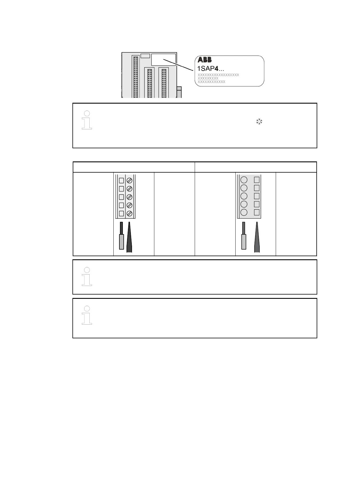
The figure 4 in the Part No. 1SAP4... (label) identifies the XC version.
Screw terminals Spring terminals
Conductor
Screwdriver Conductor
Screwdriver
(opens ter-
minal)
For information about wiring specifications see
Ä
Chapter 2.6.4.3 “Terminals at
the Terminal Unit” on page 1274.
For a detailed description of the mounting, disassembly and electrical connec-
tion of the terminal units and the I/O modules, please refer to the "System
Assembly, Construction and Connection" chapter
Ä
Chapter 2.6.3 “Mounting
and Demounting” on page 1261.
The terminals 1.8 to 4.8 and 1.9 to 4.9 are electrically interconnected within the terminal unit
and always have the same assignment, independent of the inserted module:
● Terminals 1.8 to 4.8: process supply voltage UP = +24 VDC
● Terminals 1.9 to 4.9: process supply voltage ZP = 0 V
The assignment of the other terminals depends on the inserted decentralized communication
interface module (see the description of the respective module used).
The supply voltage of 24 VDC for the module's circuitry comes from the I/O expansion bus (I/O
bus).
XC Version
Terminals
Terminal Units (AC500 Standard) > TU531 and TU532 for I/O Modules
2019/04/173ADR010121, 13, en_US166