The digital inputs can be used as source inputs or as sink inputs.
NOTICE!
Risk of malfunctions in the plant!
A ground closure, e. g. caused by a damaged cable insulation, can bridge
switches accidentally.
Use sink inputs when possible or make sure that, in case of error, there will be
no risks to persons or plant.
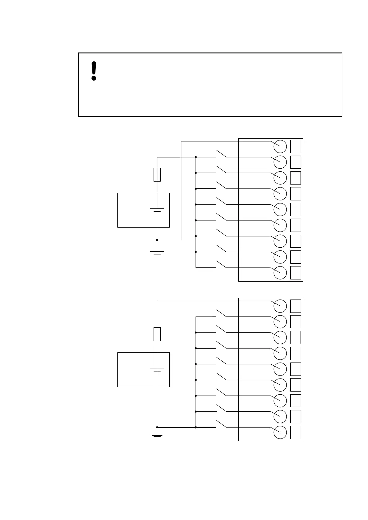
The following figures show the electrical connection of the inputs to the digital input/output
module DX571:
1
2
C0..7
I0
4
I2
24 VDC
−
+
3
I1
5
I3
6
I4
7
I5
8
I6
9
I7
Fig. 22: Electrical connection of inputs - sink inputs
1
2
C0..7
I0
4
I2
24 VDC
−
+
3
I1
5
I3
6
I4
7
I5
8
I6
9
I7
Fig. 23: Electrical connection of inputs - source inputs
The following figures show the electrical connection of the outputs to the module:
I/O Modules > Digital I/O Modules
2019/04/17 3ADR010121, 13, en_US 289