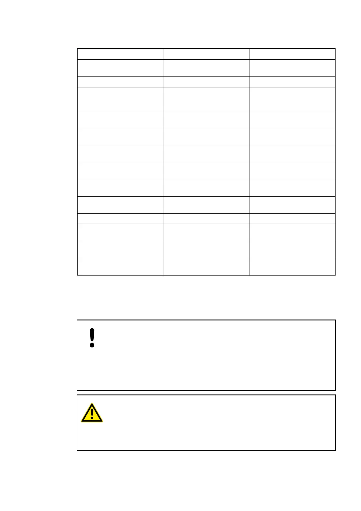
Table 51: Assignment of the other terminals:
Terminals Signal Description
1.0 to 1.7 I0 to I7 Input signals of the 8 digital
inputs
1.8 to 4.8 UP Process voltage +24 VDC
1.9 to 4.9 ZP Reference potential for the 8
digital inputs and the process
voltage
2.0 R0 Common contact of the first
relay output
3.0 NO 0 Normally-open contact of the
first relay output
4.0 NC 0 Normally-closed contact of the
first relay output
2.1 R1 Common contact of the
second relay output
3.1 NO 1 Normally-open contact of the
second relay output
4.1 NC 1 Normally-closed contact of the
second relay output
: : :
2.7 R7 Common contact of the eighth
relay output
3.7 NO 7 Normally-open contact of the
eighth relay output
4.7 NC 7 Normally-closed contact of the
eighth relay output
The internal power supply voltage for the module's circuitry is carried out via the I/O bus (pro-
vided by a bus module or a CPU). Thus, the current consumption from 24 VDC power supply at
the terminals L+/UP and M/ZP of the CPU/bus module increases by 2 mA per DX522.
The external power supply connection is carried out via the UP (+24 VDC) and the ZP (0 VDC)
terminals.
NOTICE!
Risk of damaging the PLC modules!
Overvoltages and short circuits might damage the PLC modules.
– Make sure that all voltage sources (supply and process voltage) are
switched off before you begin with operations at the system.
– Never connect any voltages or signals to reserved terminals (marked with
---). Reserved terminals may carry internal voltages.
WARNING!
Risk of death by electric shock!
The terminals of the module can carry 240 V voltage.
Make sure that all voltage sources (supply and process voltage) are switched
off before you begin with operations at the system.
The module provides several diagnosis functions (see Diagnosis and State LEDs
Ä
Chapter
1.5.1.2.8.7 “Diagnosis” on page 378).
I/O Modules > Digital I/O Modules
2019/04/173ADR010121, 13, en_US374
 Loading...


