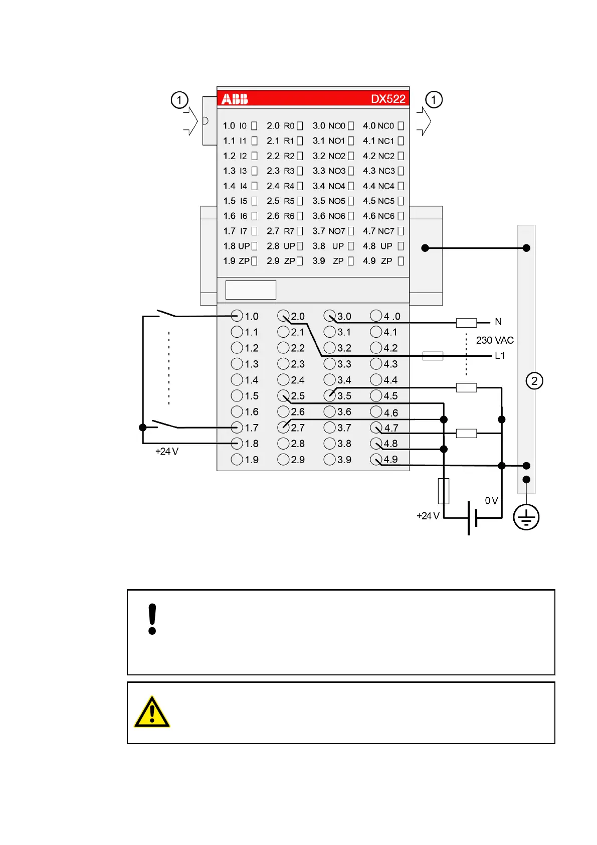
The following figure shows the electrical connection of the digital input/output module DX522.
Fig. 30: Electrical connection of the module
1 I/O bus
2 Switch-gear cabinet earth
NOTICE!
– If the relay outputs have to switch inductive DC loads, free-wheeling diodes
must be circuited in parallel to these loads.
– If the relay outputs have to switch inductive AC loads, spark suppressors
are required.
CAUTION!
The process supply voltage must be included in the earthing concept (e. g.
earthing of the minus pole).
I/O Modules > Digital I/O Modules
2019/04/17 3ADR010121, 13, en_US 375