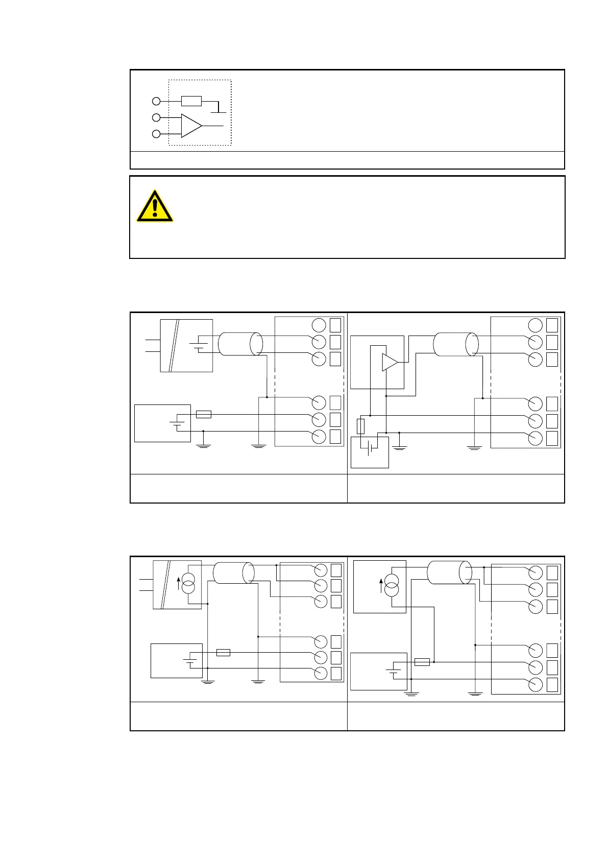
Internal construction of the analog inputs
CAUTION!
Risk of damaging the analog input!
The 250 Ω input resistor can be damaged by overcurrent.
Make sure that the current through the resistor never exceeds 30 mA.
The following figures are an example of the electrical connection of analog sensors (voltage) to
the input I0 of the analog input module AI561. Proceed with the inputs I1 to I3 in the same way.
24 VDC
−
+
1
2
R0
I0+
3
I0−
18
FE
19
L+
20
M
+
−
U
IN
−2.5 ... +2.5
V
−5 ... +5
V
0 ... 5 V
0 ... 10
V
24 VDC
−
+
1
2
R0
I0+
3
I0−
18
FE
19
L+
20
M
−2.5 ... +2.5 V
−5 ... +5 V
0 ... 5 V
0 ... 10 V
Connection of active-type analog sensors
(voltage)
Connection of passive-type analog sensors
(voltage)
The following figures are an example of the electrical connection of analog sensors (current) to
the input I0 of the analog input module AI561. Proceed with the inputs I1 to I3 in the same way.
24 VDC
−
+
1
2
R0
I0+
3
I0–
18
SG
19
L+
20
M
+
−
U
IN
4 ... 20 mA
0 ... 20 mA
24 VDC
−
+
1
2
R0
I0+
3
I0–
18
SG
19
L+
20
M
−
+
4 ... 20 mA
Connection of active-type analog sensors
(current)
Connection of passive-type analog sensors
(current)
The meaning of the LEDs is described in the Displays section
Ä
Chapter 1.5.2.1.1.7 “State
LEDs” on page 402.
I/O Modules > Analog I/O Modules
2019/04/17 3ADR010121, 13, en_US 399