After powering up the system, input channels, which are configured will have
undefined values /diagnosis message for typically 45 seconds, if the wires of all
configured channels are broken.
If the AI563 is connected to a PROFINET Bus Module, the firmware version of
PROFINET Bus Modules must be 1.2 or above.
The electrical connection is carried out by using a removable 9-pin and 11-pin terminal block.
These terminal blocks differ in their connection system (spring terminals or screw-type termi-
nals, cable mounting from the front or from the side).
Ä
Chapter 1.8.3.2 “TA563-TA565 - Ter-
minal Blocks” on page 1164. The terminal blocks are not included in the module's scope of
delivery and must be ordered separately.
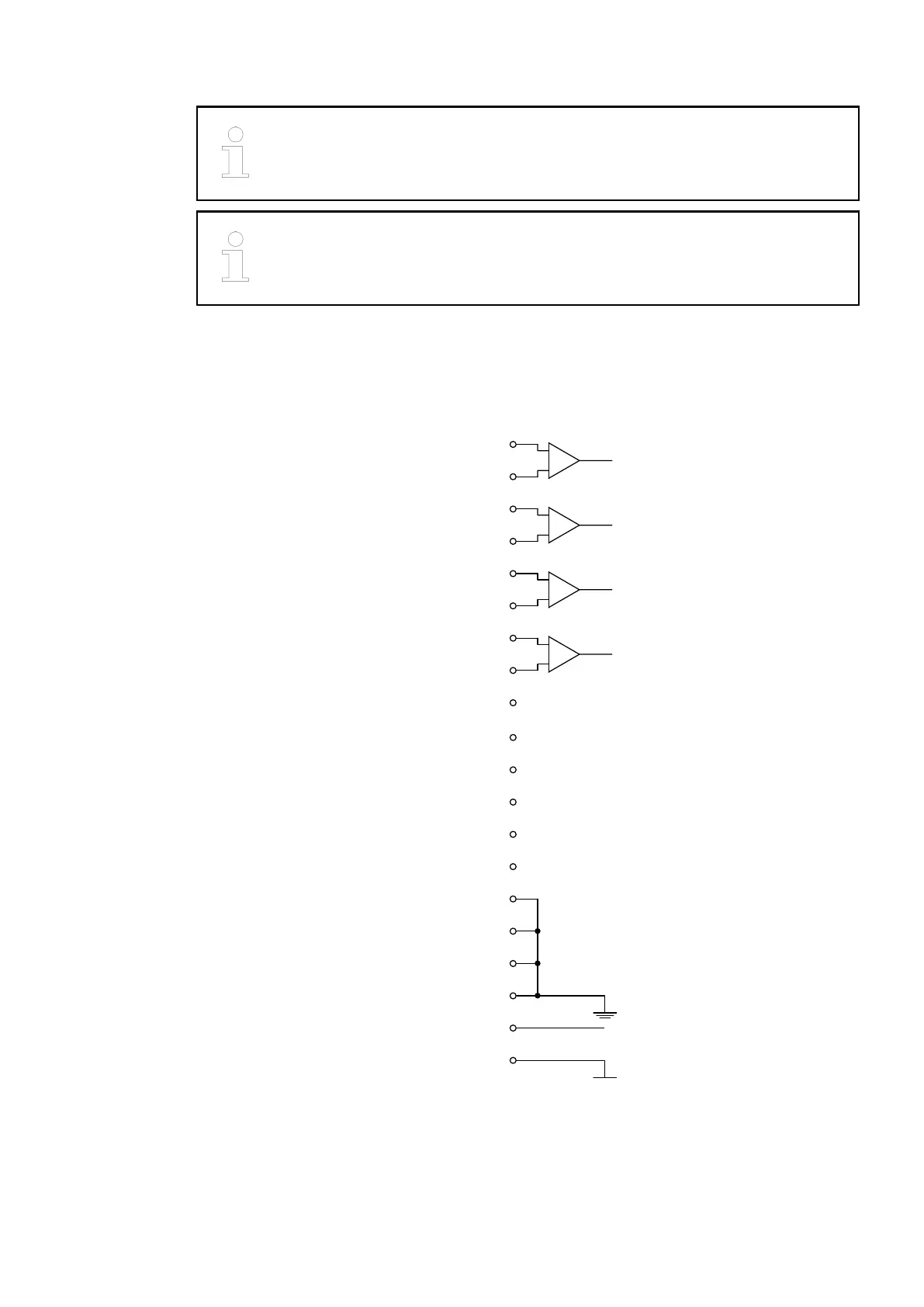
The following block diagram shows the internal construction of the analog inputs:
−−− 11
−−− 12
−−− 10
−−− 13
−−− 14
SG 16
SG 17
SG 15
UP 19
ZP 20
SG 18
I2− 6
I3+ 7
I2+ 5
+
−
I3− 8
−−− 9
I0− 2
I1+ 3
I0+ 1
+
−
I1− 4
+
−
+
−
The assignment of the terminals:
I/O Modules > Analog I/O Modules
2019/04/173ADR010121, 13, en_US418