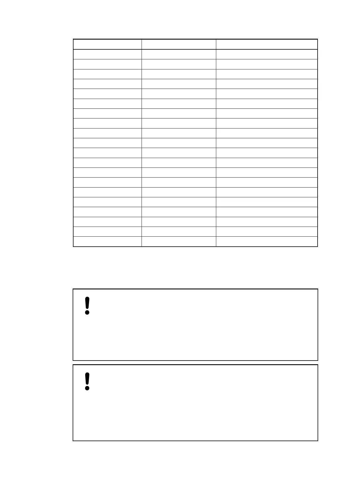
Terminal Signal Description
1 I0+ Plus pole of channel 0
2 I0- Minus pole of channel 0
3 I1+ Plus pole of channel 1
4 I1- Minus pole of channel 1
5 I2+ Plus pole of channel 2
6 I2- Minus pole of channel 2
7 I3+ Plus pole of channel 3
8 I3- Minus pole of channel 3
9 --- Reserved
10 --- Reserved
11 --- Reserved
12 --- Reserved
13 --- Reserved
14 --- Reserved
15 SG Signal ground
16 SG Signal ground
17 SG Signal ground
18 SG Signal ground
19 UP Process voltage UP (24 VDC)
20 ZP Process voltage ZP (0 VDC)
The internal power supply voltage for the module's circuitry is carried out via the I/O bus (pro-
vided by a bus module or a CPU). Thus, the current consumption from 24 VDC power supply at
the terminals UP/L+ and ZP/M of the CPU/bus module increases by 5 mA per AI563.
The external power supply connection is carried out via the UP (+24 VDC) and the ZP (0 VDC)
terminals.
NOTICE!
Risk of imprecise and faulty measurements!
Analog signals may be distorted seriously by external electromagnetic influ-
ences.
Use shielded wires when wiring analog signal sources. The cable shield must
be grounded at both ends of the cable. Provide a potential equalisation of a low
resistance to avoid high potential differences between different parts of the
plant.
NOTICE!
Risk of damaging the PLC modules!
The PLC modules must not be removed while the plant is connected to a power
supply.
Make sure that all voltage sources (supply and process voltage) are switched
off before you
– connect or disconnect any signal or terminal block
– remove or replace a module.
I/O Modules > Analog I/O Modules
2019/04/17 3ADR010121, 13, en_US 419