NOTICE!
Risk of damaging the PLC modules!
Overvoltages and short circuits might damage the PLC modules.
– Make sure that all voltage sources (supply and process voltage) are
switched off before you begin with operations at the system.
– Never connect any voltages or signals to reserved terminals (marked with
---). Reserved terminals may carry internal voltages.
The module provides several diagnosis functions
Ä
Chapter 1.5.2.1.3.6 “Diagnosis”
on page 422.
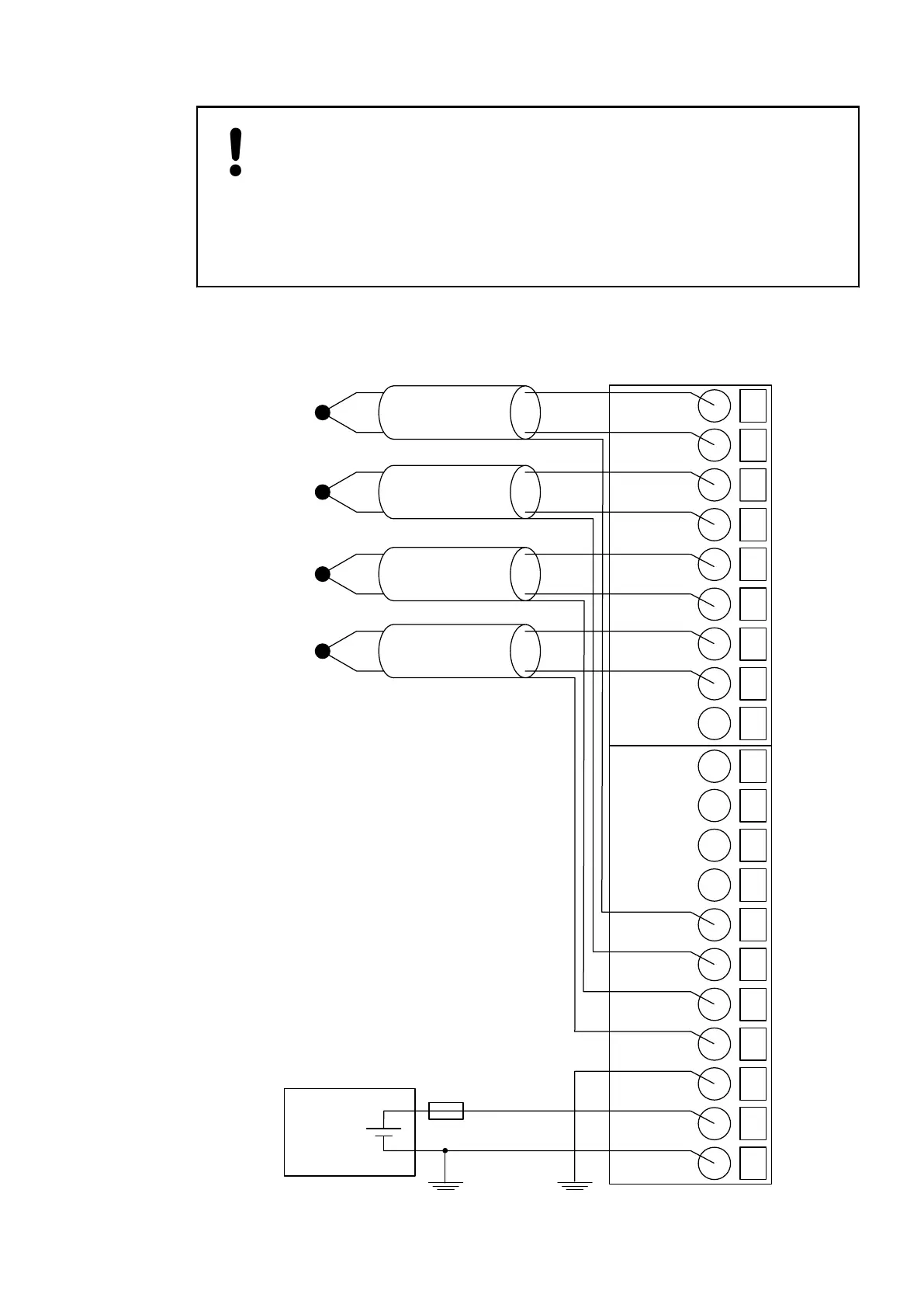
The following figure shows the electrical connection of thermocouples to the inputs of the
module:
1
2
I0+
I0−
4
I1−
24 VDC
−
+
3
I1+
5
I2+
6
I2−
7
I3+
8
I3−
9
−−−
10
11
−−−
−−−
13
−−−
12
−−−
14
FE
15
FE
16
FE
17
FE
18
FE
19
UP
20
ZP
I/O Modules > Analog I/O Modules
2019/04/173ADR010121, 13, en_US420