NOTICE!
Risk of damaging the PLC modules!
The PLC modules must not be removed while the plant is connected to a power
supply.
Make sure that all voltage sources (supply and process voltage) are switched
off before you
– connect or disconnect any signal or terminal block
– remove or replace a module.
NOTICE!
Risk of damaging the PLC modules!
Overvoltages and short circuits might damage the PLC modules.
– Make sure that all voltage sources (supply and process voltage) are
switched off before you begin with operations at the system.
– Never connect any voltages or signals to reserved terminals (marked with
---). Reserved terminals may carry internal voltages.
The module provides several diagnosis functions
Ä
Chapter 1.5.2.1.4.6 “Diagnosis”
on page 433.
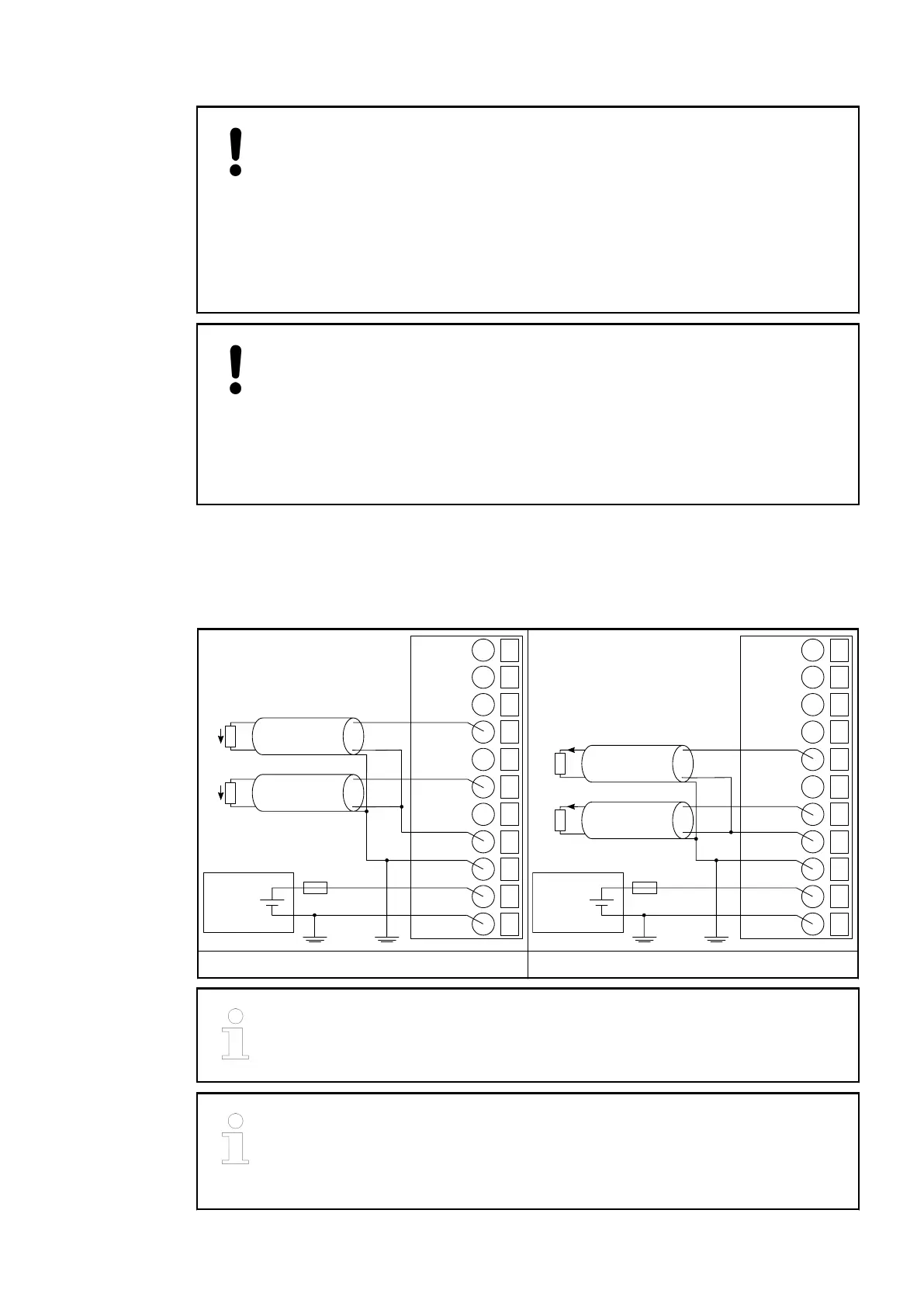
The following figures show the electrical connection of analog actuators to the analog output
module AO561.
24 VDC
−
+
10
11
−−−
−−−
13
O0U+
12
−−−
14
O0I+
15
O1U+
16
O1I+
17
O01−
18
FE
19
L+
20
M
U
U
24 VDC
−
+
10
11
−−−
−−−
13
O0U+
12
−−−
14
O0I+
15
O1U+
16
O1I+
17
O01−
18
FE
19
L+
20
M
I
I
Connection of analog voltage actuators Connection of analog current actuators
The output signal is undefined if the supply voltage at the L+ terminal is below
10 V. This can, for example, occur if the supply voltage has a slow ramp-up /
ramp-down behaviour and must be foreseen when planning the installation.
If the output is configured in current mode, the voltage output signal is unde-
fined and must not be connected.
If the output is configured in voltage mode, the current output signal is unde-
fined and must not be connected.
I/O Modules > Analog I/O Modules
2019/04/17 3ADR010121, 13, en_US 431