The terminals 1.8, 2.8, 3.8 and 4.8 as well as 1.9, 2.9, 3.9 and 4.9 are electrically intercon-
nected within the I/O terminal units and have always the same assignment, irrespective of the
inserted module:
Terminals 1.8, 2.8, 3.8 and 4.8: process voltage UP = +24 VDC
Terminals 1.9, 2.9, 3.9 and 4.9: process voltage ZP = 0 VDC
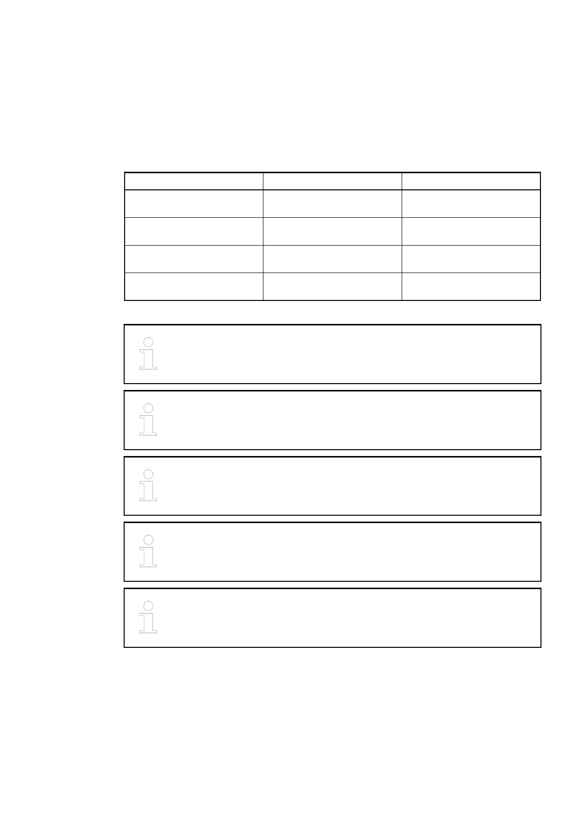
The assignment of the other terminals:
Terminals Signal Description
1.0 to 1.3 I0- to I3- Negative poles of the 4 analog
inputs
2.0 to 2.3 I0+ to I3+ Positive poles of the 4 analog
inputs
3.0 to 3.3 O0- to O3- Negative poles of the 4 analog
outputs
4.0 to 4.3 O0+ to O3+ Positive poles of the 4 analog
outputs
The negative poles of the analog inputs are electrically connected to each other
to form an "Analog Ground" signal for the module.
The negative poles of the analog outputs are electrically connected to each
other to form an "Analog Ground" signal for the module.
There is no galvanic isolation between the analog circuitry and ZP/UP. There-
fore, the analog sensors must be galvanically isolated in order to avoid loops via
the earth potential or the supply voltage.
Because of their common reference potential, analog current inputs cannot be
circuited in series, neither within the module nor with channels of other mod-
ules.
For the open-circuit detection (cut wire), each analog input channel is pulled up
to "plus" by a high-resistance resistor. If nothing is connected, the maximum
voltage will be read in then.
The internal power supply voltage for the module's circuitry is carried out via the I/O bus (pro-
vided by a bus module or a CPU). Thus, the current consumption from 24 VDC power supply at
the terminals L+/UP and M/ZP of the CPU/bus module increases by 2 mA per I/O module.
The external power supply connection is carried out via the UP (+24 VDC) and the ZP (0 VDC)
terminals.
I/O Modules > Analog I/O Modules
2019/04/173ADR010121, 13, en_US522