NOTICE!
Risk of damaging the PLC modules!
Overvoltages and short circuits might damage the PLC modules.
– Make sure that all voltage sources (supply and process voltage) are
switched off before you begin with operations at the system.
– Never connect any voltages or signals to reserved terminals (marked with
---). Reserved terminals may carry internal voltages.
Generally, analog signals must be laid in shielded cables. The cable shields
must be earthed at both sides of the cables. In order to avoid unacceptable
potential differences between different parts of the installation, low resistance
equipotential bonding conductors must be laid.
Only for simple applications (low electromagnetic disturbances, no high require-
ment on precision), the shielding can also be omitted.
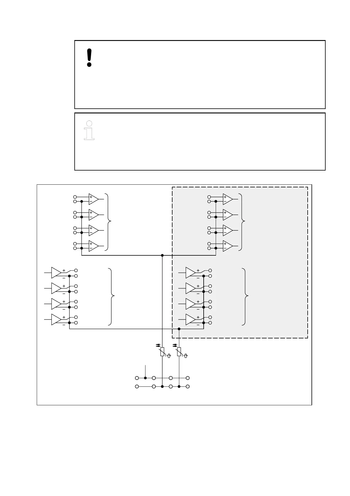
The following figure shows the electrical connection of the I/O module.
2.0
1.0
I0+
I0–
2.1
1.1
I1+
I1–
2.2
1.2
I2+
I2–
2.3
1.3
I3+
I3–
2.4
1.4
I4+
I4–
2.5
1.5
I5+
I5–
2.6
1.6
I6+
I6–
2.7
1.7
I7+
I7–
O0+
O0–
4.0
3.0
O4+
O4–
4.4
3.4
O1+
O1–
4.1
3.1
O5+
O5–
4.5
3.5
O2+
O2–
4.2
3.2
O6+
O6–
4.6
3.6
O3+
O3–
4.3
3.3
O7+
O7–
4.7
3.7
AGND
AGND
UP
ZP
1.8 2.8 3.8 4.8
1.9 2.9 3.9 4.9
+24 V
0 V
4 analog inputs
for 0...10 V,
–10 V...+10 V,
0/4... 20 mA,
Pt100 / Pt1000,
Ni1000 and
digital signals
4 analog
outputs for
–10 V...+10 V,
0/4... 20 mA
4 analog
outputs for
–10 V...+10 V
PTCPTC
4 analog inputs
for 0...10 V,
–10 V...+10 V,
0/4... 20 mA,
Pt100 / Pt1000,
Ni1000 and
digital signals
These I/Os only with AX522
Attention:
By installing equipotential
bonding conductors between
system, it must be made sure
that the potential difference
between ZP and AGND never
the different parts of the
can exceed 1 V.
Attention:
The process voltage must be
included in the earthing concept
of the control system
(e.g. earthing the minus pole).
Fig. 59: Terminal assignment
I/O Modules > Analog I/O Modules
2019/04/17 3ADR010121, 13, en_US 523