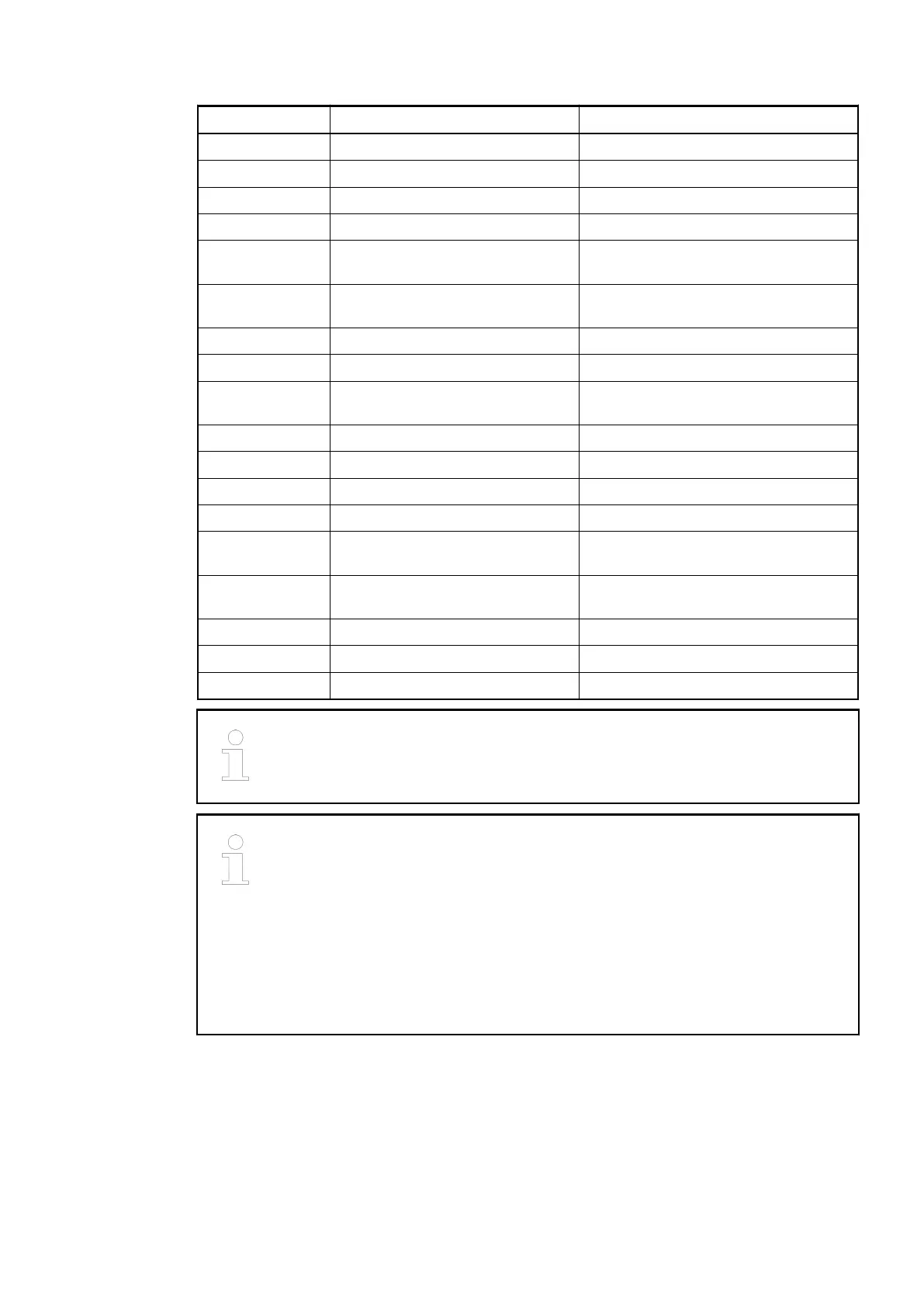
Terminal Signal Description
3 I1 Input signal I1 (stop)
4 O0 Reserved - do not connect
5 P0+ Pulse output P0+ (positive line)
6 P0- Pulse output P0- (negative line)
7 P1+ Pulse or direction output P1+ (positive
line)
8 P1- Pulse or direction output P1- (negative
line)
9 SGND Signal ground for pulse output
10 C2..3 Input common for signals I2 and I3
11 I2 Input signal I2 (axis enable and limit
switch)
12 I3 Input signal I3 (stop)
13 O1 Reserved - do not connect
14 P2+ Pulse output P2+ (positive line)
15 P2- Pulse output P2- (negative line)
16 P3+ Pulse or direction output P3+ (positive
line)
17 P3- Pulse or direction output P3- (negative
line)
18 SGND Signal ground for pulse output
19 UP Process voltage UP +24 VDC
20 ZP Process voltage ZP 0 VDC
When wiring, the motor phase line and power line should be separated in order
to avoid signal disturbances between each other.
For cable length
£
30 m, unshielded cable can be used with Baldor and BSD
servo drives normally.
For cable length > 30 m, shielded cable must be used for surge purpose.
The earthing of the shield should take place at the switch-gear cabinet, see
chapter System Data AC500
Ä
Chapter 2.6.1 “System Data AC500”
on page 1248.
The cable shields must be earthed at both ends of the cables. In order to avoid
unacceptable potential differences between different parts of the installation,
low resistance equipotential bonding conductors must be laid.
The internal power supply voltage for the module's circuitry is carried out via the I/O bus (pro-
vided by a bus module or a CPU). Thus, the current consumption from 24 VDC power supply at
the terminals L+/UP and M/ZP of the CPU/bus module increases by 5 mA per FM562.
The external power supply connection is carried out via the UP (+24 VDC) and ZP (0 VDC) ter-
minals.
Function Modules > S500-eCo
2019/04/173ADR010121, 13, en_US638