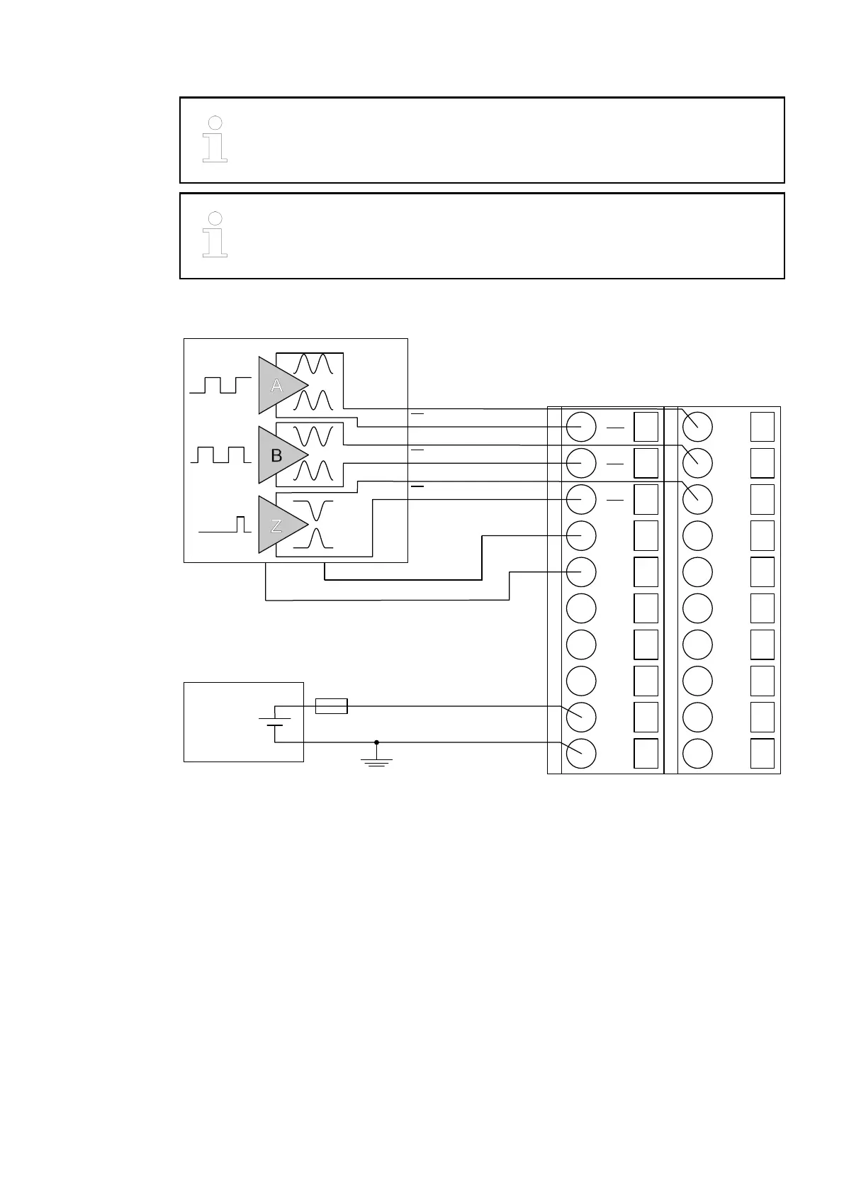
The wires A, B and Z need not to be connected to the module. They are left
open.
When using different power supplies for the encoder device and the CD522,
make sure that the reference potentials of both power supplies are intercon-
nected.
The encoder is powered through the 5 V power supply which is integrated in the CD522.
1.0
A0
1.1
B0
1.2
Z0
1.3
5V0
1.4
0V
1.5
O0
1.6
0V
1.7
O1
1.8
UP
1.9
ZP
2.0
A0
2.1
B0
2.2
Z0
2.3
I3
2.4
C4
2.5
C5
2.6
C6
2.7
C7
2.8
UP
2.9
ZP
24 V DC
−
+
A
B
Z
5 V DC
+
−
A
A
B
B
Z
Z
The encoder is powered by the 5 V power supply which is integrated in the CD522.
Connection of
Encoders with 1
Vpp Sine Signal
Connection of
Absolute
Encoders with
SSI Interface
and Differential
RS-422 Signal
2019/04/173ADR010121, 13, en_US658