1.0
A0
1.1
B0
1.2
Z0
1.3
5V0
1.4
0V
1.5
O0
1.6
0V
1.7
O1
1.8
UP
1.9
ZP
2.0
A0
2.1
B0
2.2
Z0
2.3
I3
2.4
C4
2.5
C5
2.6
C6
2.7
C7
2.8
UP
2.9
ZP
24 V DC
−
+
t
U
IN
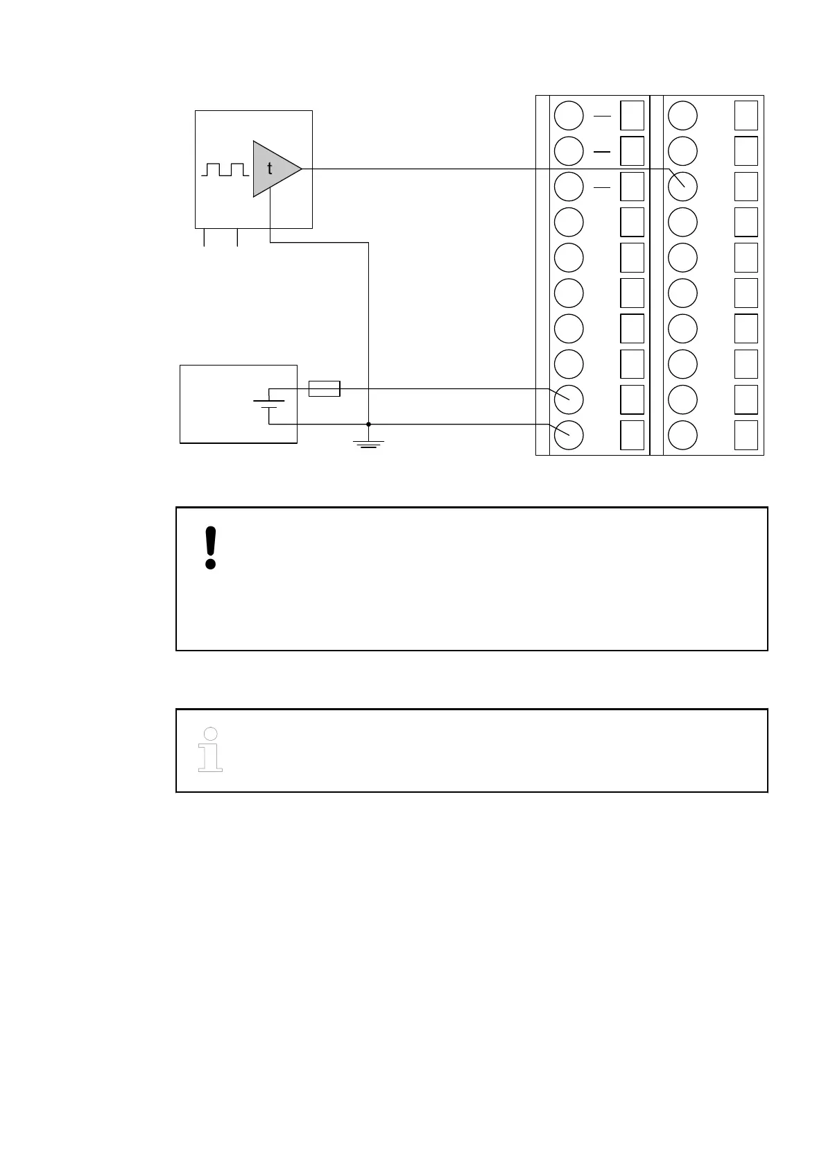
Fig. 109: Example of the electrical connection of sensors with frequency outputs to the input Z0
of the CD522
NOTICE!
Risk of malfunctions!
The edges of a signal must be strong enough (0.4 V/µs) to be recognized cor-
rectly by the module.
Put a 1 kW resistor between 0 V and the Z terminal when using a standard
output as time generator.
Proceed with the 5 V power supply 1 in the same way.
Each 5-V-power supply provides a current of 100 mA max. It is possible to par-
allel both integrated power supplies. In this case, the max. current is 200 mA.
Connection of
Sensors to the 5
V Power Supply
2019/04/17 3ADR010121, 13, en_US 661