1.0
A0
1.1
B0
1.2
Z0
1.3
5V0
1.4
0V
1.5
O0
1.6
0V
1.7
O1
1.8
UP
1.9
ZP
2.0
A0
2.1
B0
2.2
Z0
2.3
I3
2.4
C4
2.5
C5
2.6
C6
2.7
C7
2.8
UP
2.9
ZP
24 V DC
−
+
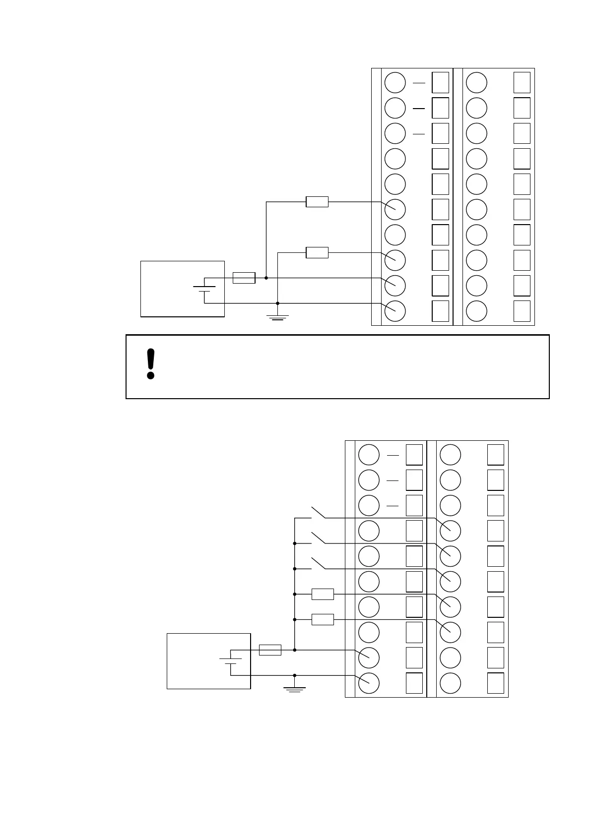
NOTICE!
Risk of damaging the Module
The PWM outputs have no protection against reverse polarity.
Proceed with the inputs/outputs I11 and C12-C15 in the same way.
1.0
A0
1.1
B0
1.2
Z0
1.3
5V0
1.4
0V
1.5
O0
1.6
0V
1.7
O1
1.8
UP
1.9
ZP
2.0
A0
2.1
B0
2.2
Z0
2.3
I3
2.4
C4
2.5
C5
2.6
C6
2.7
C7
2.8
UP
2.9
ZP
24 V DC
−
+
Proceed with the A0, B0, A1, B1 and Z1 in the same way.
Connection of
Output Loads to
the PWM/Pulse
Putputs
Connection of
Standard Inputs/
Outputs
Connection of
Sensors with
Frequency Out-
puts
2019/04/173ADR010121, 13, en_US660