NOTICE!
Attention:
All I/O channels (digital and analog) are protected against reverse polarity,
reverse supply, short circuit and continuous overvoltage up to 30 VDC.
Multiple overloads
No effects of multiple overloads on isolated multi-channel modules occur, as
every channel is protected individually by an internal smart high-side switch.
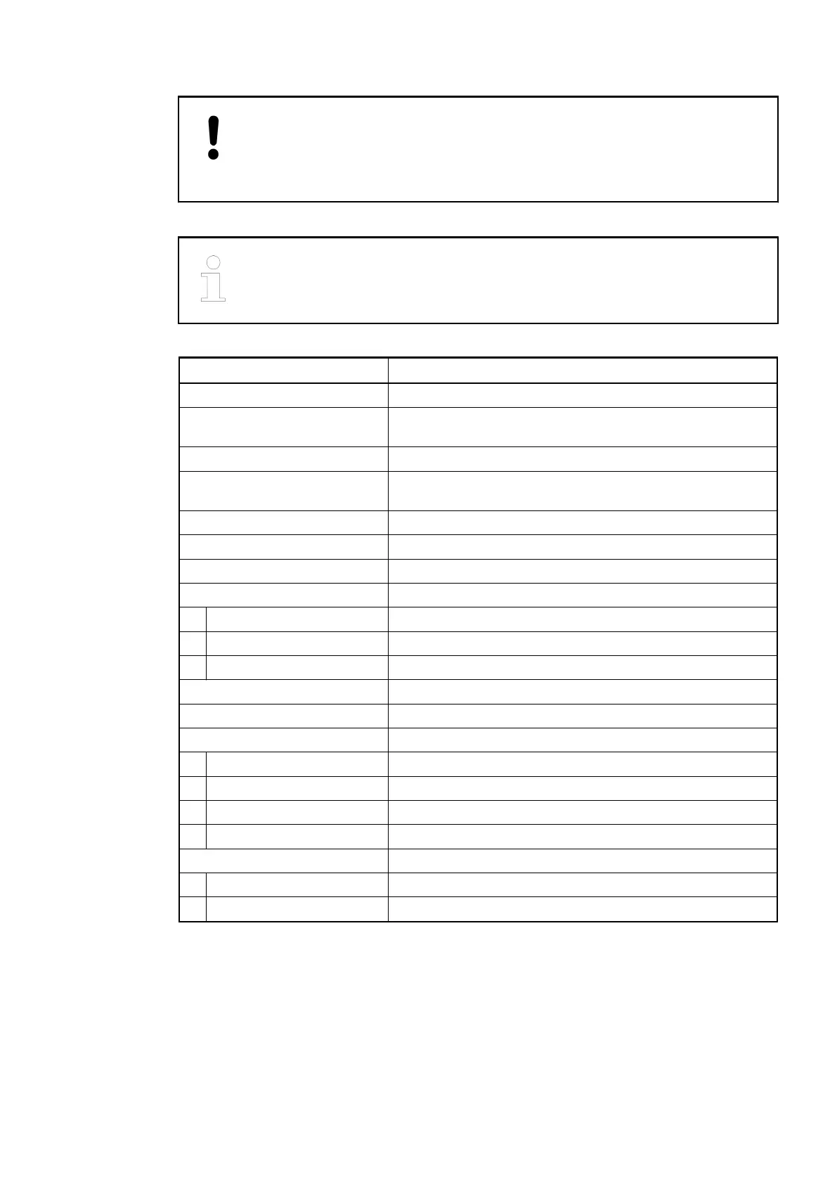
Parameter Value
Number of channels 2 + 8 configurable digital inputs/outputs
Reference potential for all
inputs
Terminals 1.9...4.9 (negative pole of the process supply
voltage, signal name ZP)
Galvanic isolation From the rest of the module
Indication of the input signals 1 yellow LED per channel, the LED is ON when the input
signal is high (signal 1)
Input type acc. to EN 61131-2 Type 1
Input delay (0->1 or 1->0) Typ. 8 ms, configurable from 0.1 to 32 ms
Input data length 24 bytes
Input signal voltage 24 V DC
Signal 0 -3 V...+5 V *
Undefined signal > +5 V...< +15 V
Signal 1 +15 V...+30 V
Ripple with signal 0 Within -3 V...+5 V *
Ripple with signal 1 Within +15 V...+30 V
Input current per channel
Input voltage +24 V Typ. 5 mA
Input voltage +5 V > 1 mA
Input voltage +15 V > 5 mA
Input voltage +30 V < 8 mA
Max. cable length
Shielded 1000 m
Unshielded 600 m
* Due to the direct connection to the output, the demagnetizing varistor is also effective at the
input (see figure) above. This is why the difference between UPx and the input signal must not
exceed the clamp voltage of the varistor. The varistor limits the clamp voltage to approx. 36 V.
Consequently, the input voltage must range from -12 V to +30 V when UPx = 24 V and from
-6 V to +30 V when UPx = 30 V.
Technical Data
of the Digital
Inputs/Outputs
if Used as
Standard Inputs
2019/04/173ADR010121, 13, en_US670