Parameter Value
Number of channels 8 configurable digital inputs/outputs
Reference potential for all outputs Terminals 1.9...4.9 (negative pole of the process
supply voltage, signal name ZP)
Common power supply voltage For all outputs: terminals 1.8...4.8 (positive pole
of the process supply voltage, signal name UP)
Output voltage for signal 1 UP (-0.8 V)
Output delay (0->1 or 1->0) Typ. 10 µs
Output data length 32 bytes
Output current
Rated value, per channel 500 mA at UP = 24 V
Maximum value (all channels together,
PWM included)
8 A
Leakage current with signal 0 < 0.5 mA
Rated protection fuse on UP 10 A fast
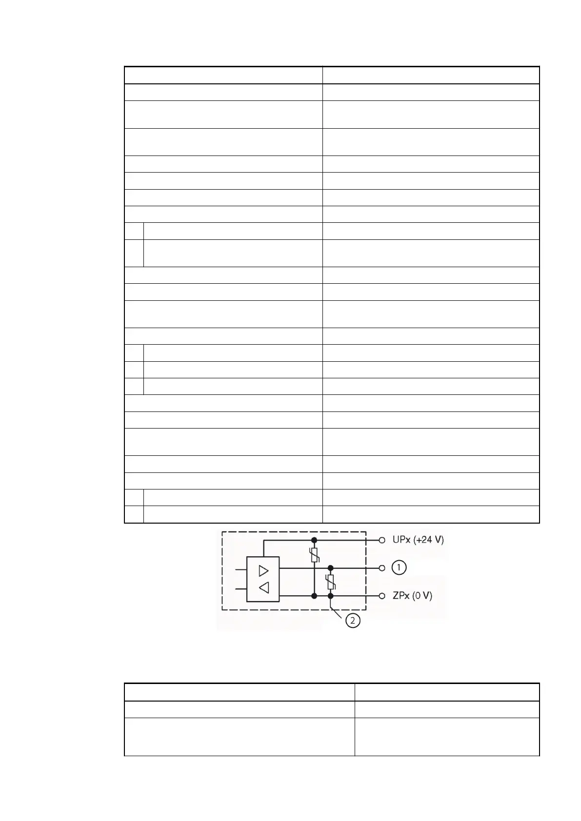
Demagnetization when inductive loads are
switched off
With varistors integrated in the module (see
figure below)
Switching frequency
With resistive load On request
With inductive loads Max. 0.5 Hz
With lamp loads Max. 11 Hz with max. 5 W
Short-circuit-proof / overload-proof Yes
Overload message (I > 0.7 A) Yes, after ca. 100 ms
Output current limitation Yes, automatic reactivation after short circuit/
overload
Resistance to feedback against 24 V signals Yes
Max. cable length
Shielded 1000 m
Unshielded 600 m
Fig. 110: Circuitry of a digital input/output with the varistors for demagnetization when inductive
loads are switched off
Parameter Value
Number of channels per module 6
Reference potential for all inputs Terminal 1.9, 2.9, 3.9 and 4.9 (negative
pole of the process voltage, signal name
ZP)
Technical Data
of the Digital
Inputs/Outputs
if Used as
Standard Out-
puts
Technical Data
of the High-
Speed Inputs
(A0, B0, Z0; A1,
B1, Z1)
2019/04/17 3ADR010121, 13, en_US 671