NOTICE!
If A- is not connected directly to M at the sensor, the supply current flows via A-
to M. Measuring errors can occur caused by voltage differences between M and
A-.
NOTICE!
At system start up, the 4 mA current source on each analog input is active for <
10 s. During this limited time, a positive analog input will drift to < 21 V and no
current is flowing, when a high impedance sensor is connected. When a low
impedance sensor is connected to the analog input, the current is limited to 4
mA. For analog sensors other than standard IEPE, please make sure that the
connected sensor will not be damaged under these conditions.
Analog signals must be laid in shielded cables. The analog cable shield must only be connected
on the module side (SH terminals) to avoid relaxation currents influencing the measuring
results, and for optimal robustness against external noise. The shield connection must be as
short as possible (< 3 cm). The analog shield is capacitive coupled internally with functional
earth (FE). Generally to avoid unacceptable potential differences between different parts of the
installation, low-resistance equipotential bonding conductors must be laid.
In order to avoid error messages or long processing times, it is recommended to configure
unused analog input channels as "unused".
In order to avoid inaccuracy in the analog measurement, the FM502-CMS should be in thermal
balance > 15 minutes after power up and start of the PLC application, before measurements are
started.
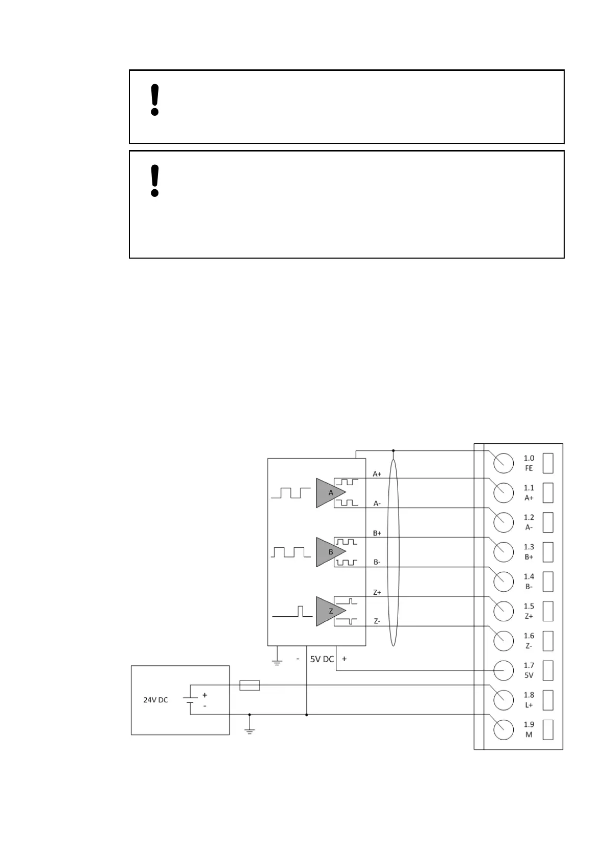
The encoder is powered by the 5 V power supply which is integrated in the FM502-CMS.Connection of
Encoders with
Differential
RS-422 Signal
2019/04/17 3ADR010121, 13, en_US 679