1.0
1.1
1.2
1.3
1.4
1.5
1.6
1.7
1.8
1.9
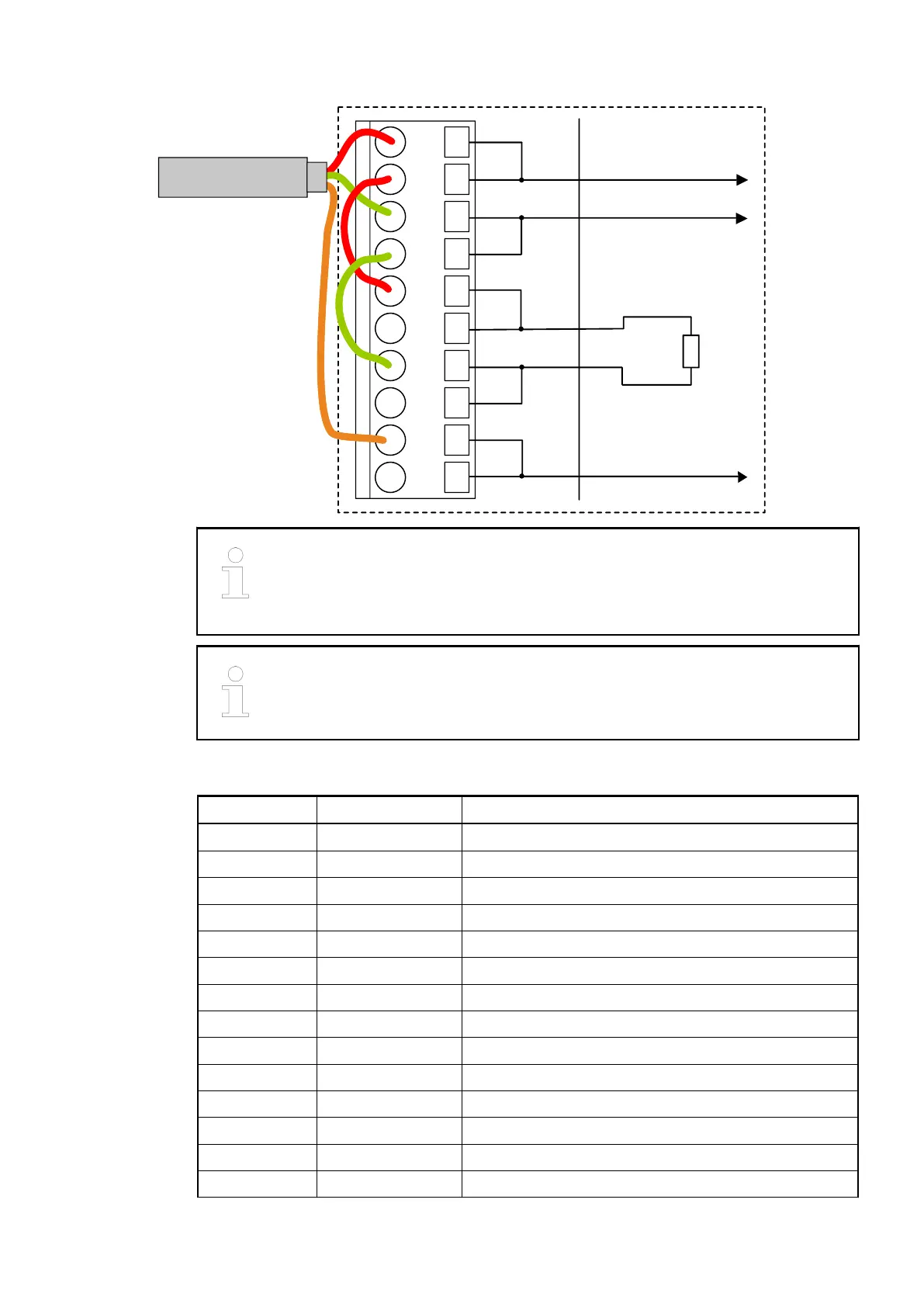
CANopen end
In the case of TU517/TU518, the termination resistors are not located inside the
TU but inside the bus module CI581-CN. Hence, when removing the device
from the TU, the bus termination resistors are no longer connected to the bus.
The bus itself will not be disconnected if a device is removed.
The earthing of the shield should take place at the switch-gear cabinet. Please
refer to the AC500 System-Data
Ä
Chapter 2.6.1 “System Data AC500”
on page 1248.
Table 118: Assignment of the other Terminals
Terminal Signal Description
2.0 DC0 Signal of the configurable digital input/output DC0
2.1 DC1 Signal of the configurable digital input/output DC1
2.2 DC2 Signal of the configurable digital input/output DC2
2.3 DC3 Signal of the configurable digital input/output DC3
2.4 DC4 Signal of the configurable digital input/output DC4
2.5 DC5 Signal of the configurable digital input/output DC5
2.6 DC6 Signal of the configurable digital input/output DC6
2.7 DC7 Signal of the configurable digital input/output DC7
2.8 UP Process voltage UP (24 VDC)
2.9 ZP Process voltage ZP (0 VDC)
3.0 DI8 Signal of the digital input DI8
3.1 DI9 Signal of the digital input DI9
3.2 DI10 Signal of the digital input DI10
3.3 DI11 Signal of the digital input DI11
Communication Interface Modules (S500) > CANopen
2019/04/173ADR010121, 13, en_US744