2-274 MACHINE OPERATIONS OPERACIONES DE MECANIZADO
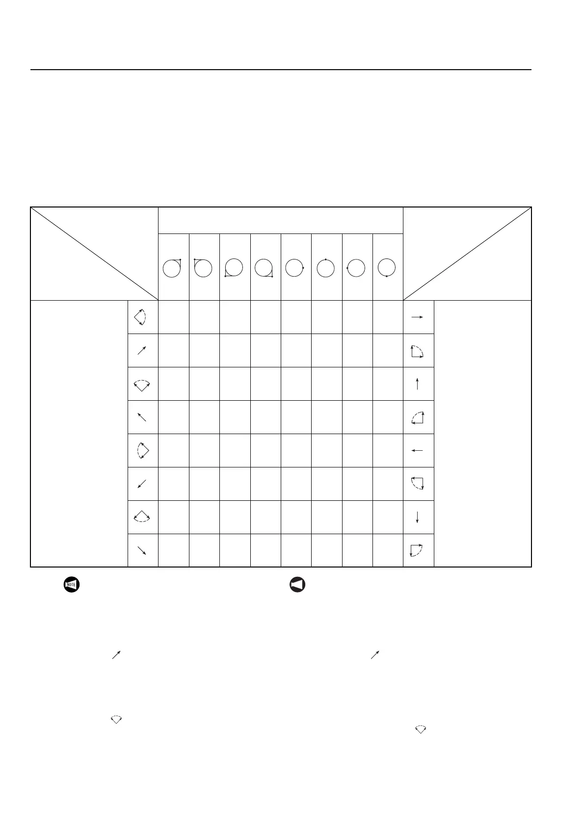
15-2-4 Direction of Offset Determined by G46
Dirección de la corrección determinada por G46
If the G41 or G42 command is used to call up the
tool nose radius offset function, the direction of offset
is determined by the specified G command. In com-
parison to these G commands, the G46 command is
used to call up the tool nose radius offset function in
which the direction of offset is automatically deter-
mined from the imaginary tool tip position and the
direction of movement in the manner indicated in the
table below.
Si se utiliza el comando G41 o G42 para llamar a la función de
corrección del radio de la nariz de herramienta, el comando G
especificado determina la dirección de la corrección. En com-
paración con esos comandos G, el comando G46 se utiliza
para llamar a la función de corrección del radio de la nariz de
herramienta. En dicha función, la dirección de la corrección
desde la posición de la punta de la herramienta imaginaria así
como la dirección del movimientose se determinan automáti-
camente de la forma que se indica en la siguiente tabla.
Offset Direction
Dirección de
corrección
Tool Nose
Moving
Direction
Dirección del
desplazamiento de
la nariz de herramienta
Imaginary Tool Tip Position
Posición de la punta de la herramienta imaginaria
Offset Direction
Dirección de
corrección
Tool Nose
Moving
Direction
Dirección del
desplazamiento de
la nariz de herramienta
Moving Direction
(imaginary tip
position: 1 to 4)
Dirección del despla-
zamiento
(posición de la punta
imaginaria: 1 a 4)
Right
dere-
cha
Right
dere-
cha
Left
IZqrda
Left
IZqrda
×
Right
dere-
cha
×
Left
IZqrda
Moving Direction
(imaginary tool tip
position: 5 to 8)
Dirección del despla-
zamiento
(posición de la punta
de la herramienta
imaginaria: 5 a 8)
×
Right
dere-
cha
×
Left
IZqrda
Left
IZqrda
Right
dere-
cha
Right
dere-
cha
Left
IZqrda
Left
IZqrda
Right
dere-
cha
Right
dere-
cha
Left
IZqrda
Left
IZqrda
×
Right
dere-
cha
×
Left
IZqrda
×
Right
dere-
cha
×
Left
IZqrda
Left
IZqrda
Right
dere-
cha
Right
dere-
cha
Left
IZqrda
Left
IZqrda
Right
dere-
cha
Right
dere-
cha
×
Left
IZqrda
×
Right
dere-
cha
×
Left
IZqrda
×
Right
dere-
cha
Right
dere-
cha
Left
IZqrda
Left
IZqrda
Right
dere-
cha
Right
dere-
cha
Left
IZqrda
Left
IZqrda
Right
dere-
cha
Right
dere-
cha
×
Left
IZqrda
×
Right
dere-
cha
×
Left
IZqrda
×
Left
IZqrda
Right
dere-
cha
Left
IZqrda
Left
IZqrda
1
2
3 4
5
6
7
8
1. The cross symbol (×) indicates that the
direction of offset cannot be determined
from the programmed direction of axis
movement and the imaginary tool tip posi-
tion.
2. Arrow symbols indicate the direction of
tool tip (axes) movements. The symbol
( ), for example, indicates the axes (tool
tip) move in the 45° direction.
3. If the tool tip (axes) movement direction is
indefinite and can be determined only in a
certain range, it is expressed by two arrow
symbols with arc in dots. The symbol
( ), for example, indicates that the axes
(tool tip) move in the range from 45° to
135°.
NOT A
1. El símbolo del aspa (×) indica que la dirección de
corrección no puede determinarse a partir de la
dirección programada del movimiento del eje y de
la posición de la punta de la herramienta imagina-
ria.
2. Las flechas indican la dirección de los desplaza-
mientos de la punta de la herramienta (ejes). El
símbolo ( ), por ejemplo, indica que los ejes
(punta de la herramienta) se desplazan en la
dirección del ángulo de 45°.
3. Si la dirección del movimiento de la punta de la
herramienta (ejes) es indefinida y puede determi-
narse únicamente en un intervalo concreto, se
expresa mediante flechas punteadas y en forma
de arco. El símbolo ( ), por ejemplo, indica que
los ejes (punta de la herramienta) se desplazan
en el ángulo comprendido entre los 45° y los
135°.
 Loading...