2-555MACHINE OPERATIONS OPERACIONES DE MECANIZADO
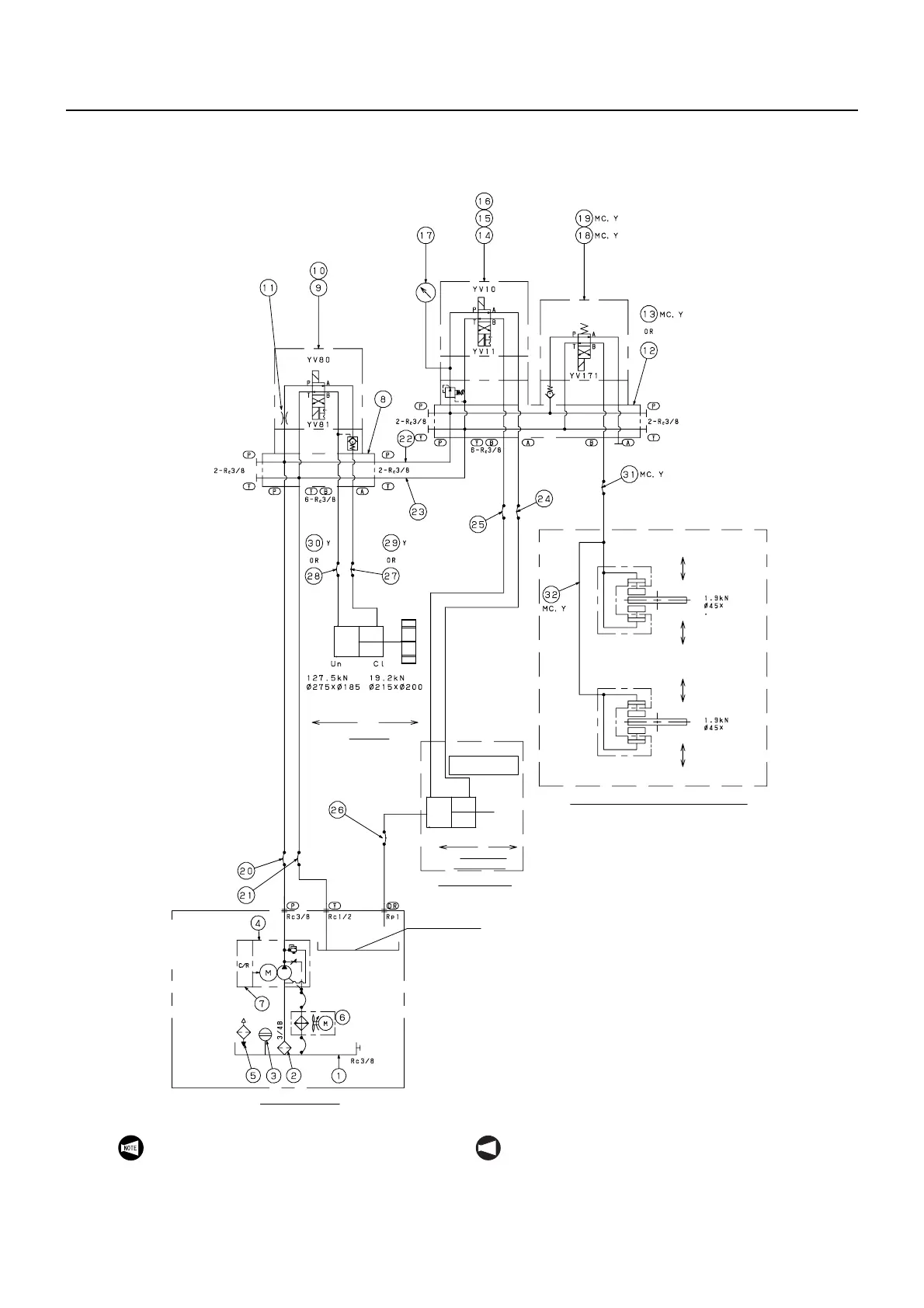
28-10-11 Hydraulic Circuit Diagram (NL3000/700)
Diagrama del circuito hidráulico (NL3000/700)
(Q40060 001)
∗LIBERACIÓN
∗UNCLAMP
∗LIBERACIÓN
∗UNCLAMP
∗LIBERACIÓN
∗UNCLAMP
∗LIBERACIÓN
∗UNCLAMP
SUJECIÓN
CLAMP
SUJECIÓN
CLAMP
SUJECIÓN
CLAMP
LIBERACIÓN
UNCLAMP
∗SUJECIÓN
∗CLAMP
SUJECIÓN
CLAMP
Carrera 0,5
Stroke 0.5
Carrera 0,5
Stroke 0.5
Configure a
4,0 MPa
Set 4.0 MPa
Unidad hidráulica
Hydraulic unit
Calibrador
de la presión
de sujeción
Presión
máxima
permitida:
6,9 MPa
Chucking
pressure gage
Max.
permissible
pressure:
6.9 MPa
Carrera 3
Stroke 3
Carrera 3
Stroke 3
Torreta
Turret
Cilindro & plato
Chuck & cylinder
∗CERRAR
ABRIR
∗CLOSE
OPEN
Plato del husillo 1
Spindle 1 chuck
Por encima de la
superficie de aceite
Above oil surface
Sujeción
Chucking
Configurado para
que se DESACTIVE
a una presión de
2,0 MPa o inferior
Set to turn OFF at
2.0 MPa or less
C-axis brake (only for NL3000MC and NL3000Y)
Freno del eje C
(exclusivo para los modelos NL3000MC y NL3000Y)
1. The asterisk indicates the zero position.
2. MC: NL3000MC Specifications Only
Y: NL3000Y Specifications Only
NOT A
1. Un asterisco indica la posición cero.
2. MC: Especificaciones exclusivas del modelo
NL3000MC
Y: Especificaciones exclusivas del modelo
NL3000Y
 Loading...