2-639MACHINE OPERATIONS OPERACIONES DE MECANIZADO
20) Turn OFF the main power.
21) Remove the lever type dial test indicators.
22) Return the turret X-axis cover to its original posi-
tion and tighten the 7 screws to secure.
23) Remount the turret front and side covers by fol-
lowing the removal procedure in reverse.
24) Remount the turret surrounding covers (Z-axis
protector and saddle side cover) by following the
removal procedure in reverse.
25) Remount the maintenance cover and machine
rear cover.
20) DESCONECTE la alimentación principal.
21) Extraiga el indicador de prueba mediante un calibrador
de dial.
22) Haga regresar la cubierta del eje X de la torreta a su
posición original y ciña los 7 tornillos de sujeción.
23) Vuelva a instalar las cubiertas laterales y frontal de la
torreta siguiendo en orden inverso el procedimiento de
retirada.
24) Vuelva a instalar las cubiertas que rodean la torreta
(cubierta lateral del carro y cubierta protectora del eje Z)
siguiendo el procedimiento de retirada en orden inverso.
25) Vuelva a instalar la cubierta de mantenimiento y la de la
parte trasera de la máquina.
29-10-4 Turret Center-Height Adjustment
Ajuste de la altura del centro de la torreta
If unmachined material is left in the center during
edge face machining of the chuck work, perform tur-
ret center-height adjustment according to the follow-
ing procedure.
<Necessary Tools>
• Lever type dial test indicators
• Lever type dial test indicators mounting jig
• Hex wrench
<Procedure>
1) Perform a Z-axis zero point return.
2) Open the operator door.
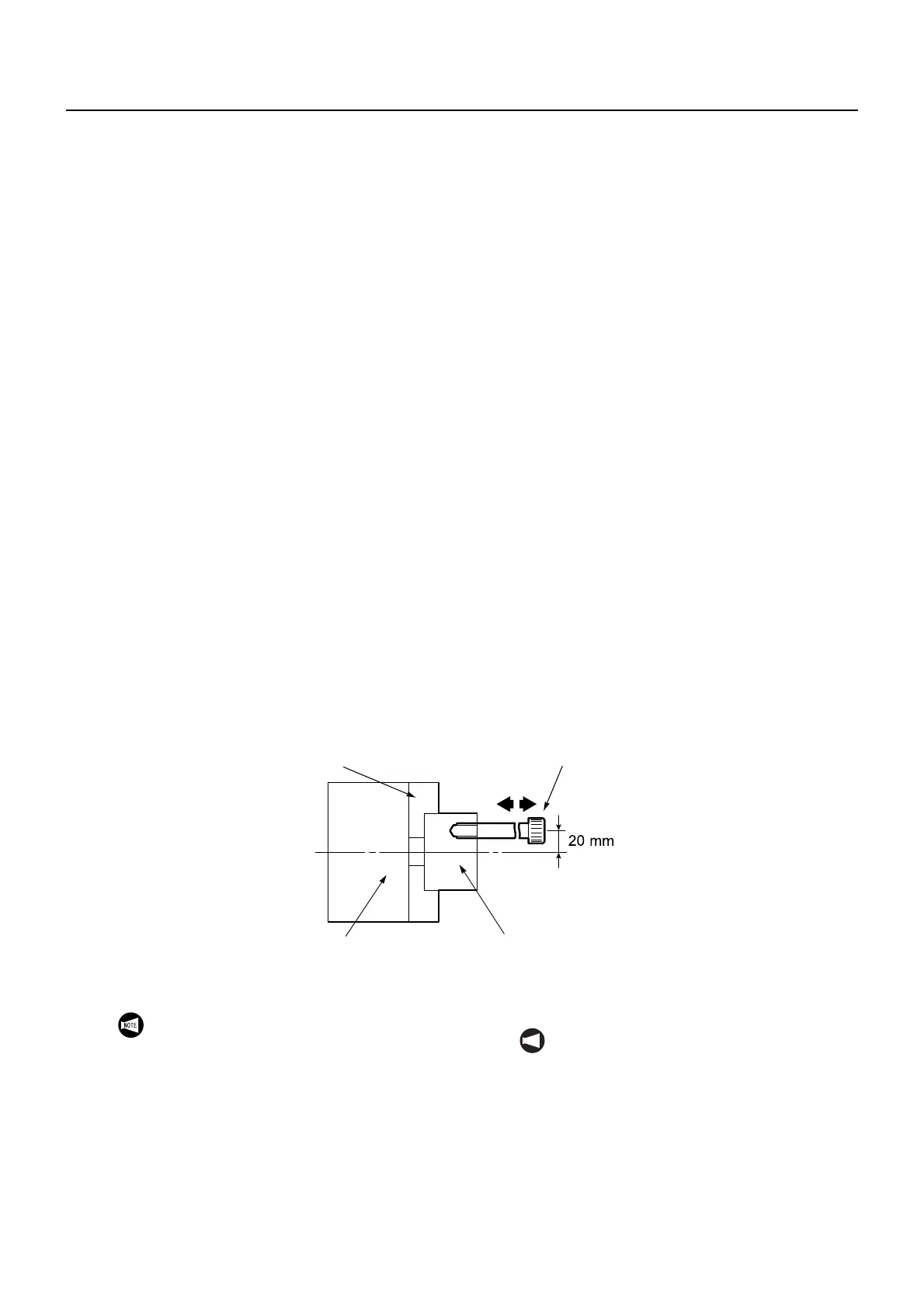
3) Clamp an appropriate sized workpiece in the
chuck and prepare a lever type dial test indica-
tors mounting jig to the dimensions shown in the
diagram below.
Si se deja material sin mecanizar en el centro durante el
mecanizado de la superficie del borde de la pieza del plato,
realice la regulación de altura del centro de la torreta
siguiendo el procedimiento que se expone a continuación.
<Herramientas necesarias>
• Indicadores de prueba mediante un calibrador de dial
• Mordaza de instalación de los indicadores de prueba
mediante un calibrador de dial
• Llave hexagonal
<Procedimiento>
1) Ejecute un retorno al punto cero del eje Z.
2) Abra la puerta del operador.
3) Sujete una pieza de tamaño adecuado en el plato y
prepare una mordaza de instalación de los indicadores
de prueba mediante un calibrador de dial según las
dimensiones que se muestran en el siguiente diagrama.
4) Mount a lever type dial test indicators on the jig.
5) Mount a boring bar holder with an I.D. of 40 mm
in the turret head indexing position.
4) Instale un indicador de prueba mediante un calibrador
dial en la mordaza.
5) Instale un soporte de la barra de mandrinar con un D.I.
de 40 mm en la posición de indización del cabezal de la
torreta.
Soft Jaw
Mordazas blandas
M10 Cap Bolt
M10 Perno de cabeza
Chuck
Plato
Appropriate Sized Workpiece
Pieza de tamaño adecuado
Mounting a lever type dial test indicators on the
spindle with a magnet stand will result in
measurement inaccuracy due to gravitational
force. Use a lever type dial test indicators
mounting jig at all times when performing this
procedure.
NOT A
La instalación de un indicador de prueba
mediante un calibrador de dial en el husillo con
un soporte magnético provocará una
imprecisión en la medición debido a la fuerza
de la gravedad. Utilice siempre una mordaza
de instalación del indicador de prueba
mediante un calibrador de dial cuando lleve a
cabo este procedimiento.
 Loading...